introduction, first impressions, questions

Hi everyone

I have been silently lurking and reading the forums for a couple of weeks.. and finally have something worthwhile to post.

I am Bert from Rotterdam, the netherlands and last friday I bought the M200!

I have been doubting to purchase this machine for a couple of weeks. I had 2 options for distinct reasons. An ultimaker original or the M200.

I have some experience with the ultimaker being a teacher in the digital station at an art academy one day a week and my 'doubt' mainly was

which direction to take; buy an ultimaker and start tinkering on the machine, investing time (and play) with the settings in cura/slic3r/repetier, experimenting with materials etc or just to push some buttons and focus more on the designs then on the machine itself.  I chose the latter but untill the end my main worries were the possible limitations in z-suite.

So I bought I bought the M200 at Ridix, a local official reseller of Zortrax last friday ( good to have a place around the corner were they sell filaments etc). and have been experimentating since  :-)

First impressions:

getting it out of the box: What a well build machine! Feels/looks like a tool and not a toy. Loved the details in the box like the tools.

assembly was very easy (some drawing in the manual were not very clear to me) and had it calibrated 30 minutes after unboxing.

First print.

Just printed a new filament holder because I didn't like the orange one that came with my machine.  Came out in great in Ultra-T except 2 burn marks.

First Challenge:

this is a lamp a recently made from paper, it's a dodecahdron made up of 31 elements.  The paper is subject to humidity, stains etc and I am curious to see if I can print it. You can see it working here: http://www.bertsimons.nl/portfolio/WIP/isoled/  

It also seemed a good practice/challenge to try to  get a 'reproducable' series with 'product' qualities and not just to print a thingiverse thingy.

With a special challenge to get the material as translucent as possible without a transparent material being avalaible..

afbeelding.jpgP1020493.jpg

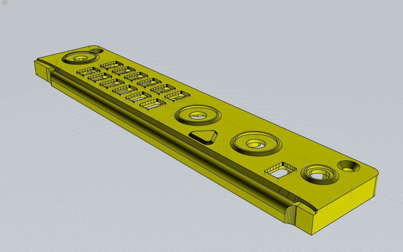
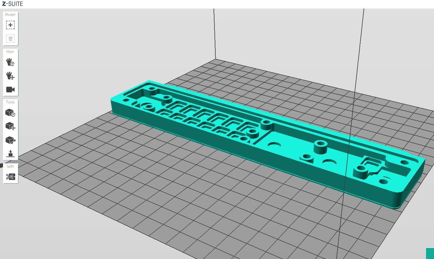
So because the light has to shine through material thickness should be as thin as possible. And I drew this in rhino with a wall thickness of 0.8mm

rhino.jpg

first print.

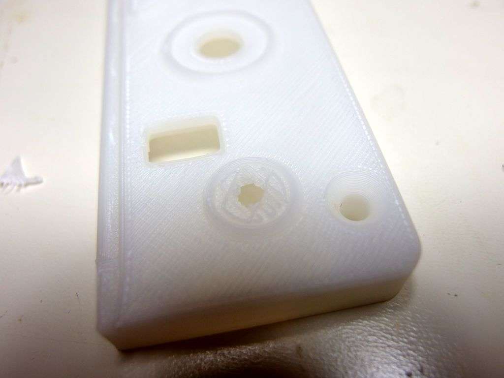
I placed the element with the wide side down and printed it in utra-t. Used light support and this came out.

unfortunaly my second print also had some burns..

P1070724.jpg

I could easily remove the raft from the inside and the light support.

P1020806.jpg

unfortunatly I was not able to remove the 'solid' raft on top of the support.. and there's a burn in the top too..

P1020826.jpg

So I decided to print it with the top at the bottom, also didn't like the 'normal seam' which you can see in the middle top part of the picture above and choose for random seams for the next print.

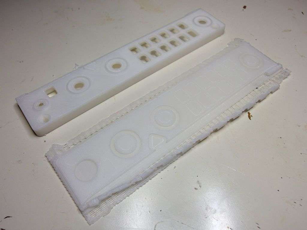
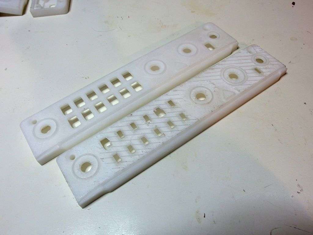
left print is with ultra-t, right one wih z-abs.

The ultra print came off the raft quitte good, the surface was still quitte reflective, The ABS one hower had clearly visible surface 'damage' where it was attached to the raft.

P1020829.jpg

here you see the ''damage" in ABS  when I put a light behind it.. damned why do I want to make a lamp shade?

P1020830.jpg

turning the seams from normal to random did not give a better result. Z-suite placed the seams at the edges of the surfaces, for each layer random at one of the edges showing of as blobs on the edges.

what I miss at this point is the ability to spiral print, without stopping/starting printhead at different locations.  I solved this however by givving the edges a fillet. this reduced the blobs.

P1020831.jpg

I really liked the abs look. besides the problem of having the top of the shape on the raft with visible marks when removing..

printing with the top up gave the problem of not being able to remove the 'solid' raft layer (which would probably also have given some visible removal marks.)

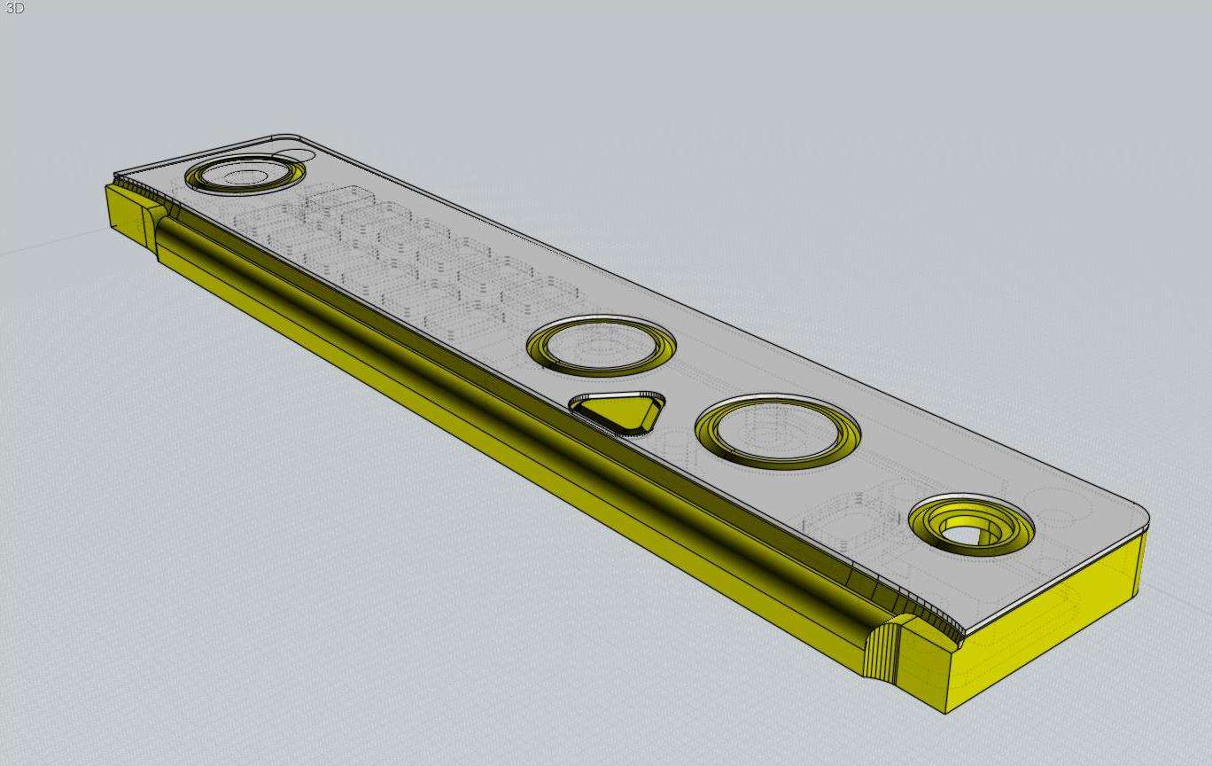
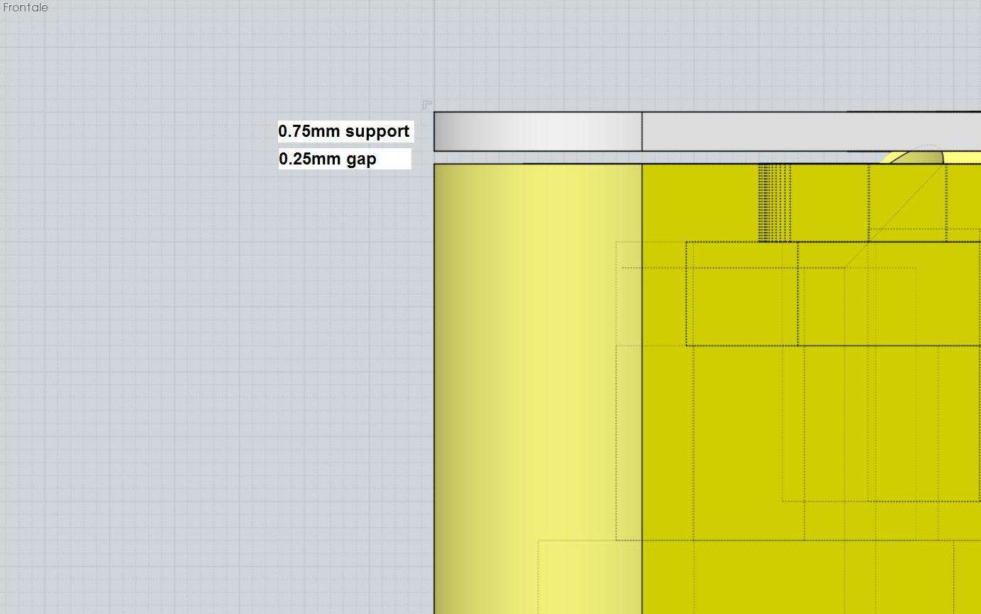
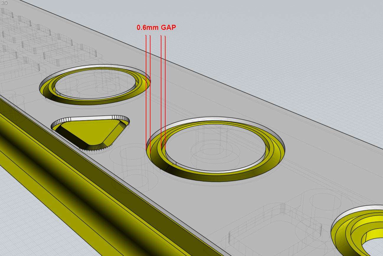
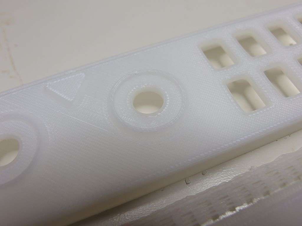
but I thought I could solve that by making a custom support underneath the top which does not touch the top at the inside.. 

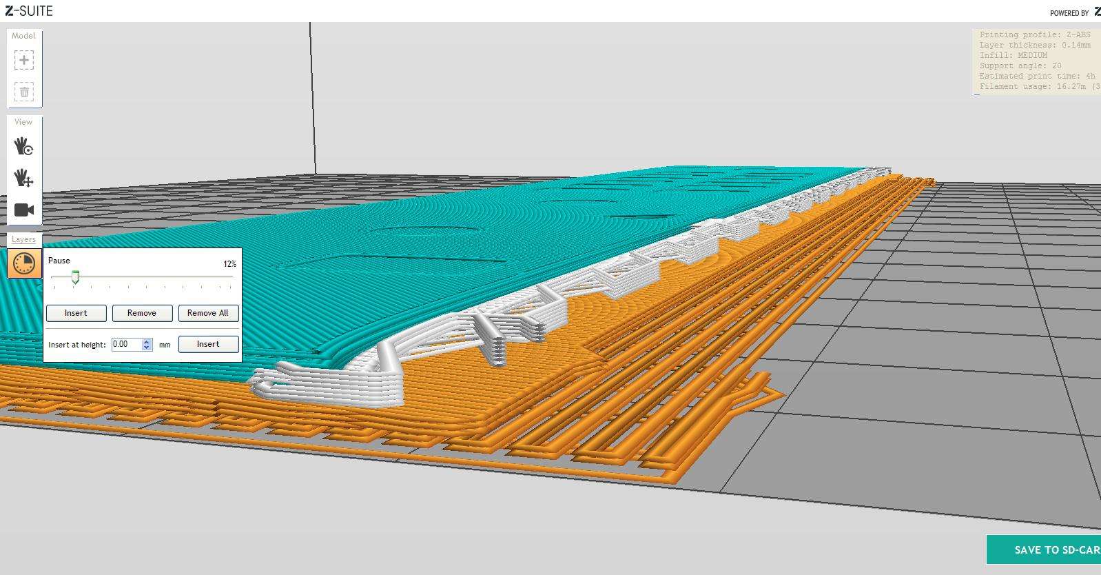
So I draw a solid layer just beneath the top (0,1 mm) which hopely would result in some mid-air printing without the filament dropping to much to prevent next layer to stick but with the air gap far enouvh to not get next layers stick to it..

customsupport.png

and to my big suprise.. it workes, I could remove inner support very easy and the solid custiom support plate only sticked to the lite support :-)

When I hold it against light it is very acceptable

P1020836.jpg

But, this method in ABS with the top side up, the support lite and the extra support made print times a lot longer..

So I decided to do the ultra-t with top on heatbed which also looked quitte good.

Conclusion:

So this was my first printing experiment...

I am very pleased with the quality of the zortrax!  ( except for the burns.. which have happened a few times more.)

Yes I do miss some extra (software) functionallity at moment but I think the print quality is a bigger plus for me now.

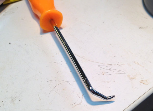
Things I didn't like:

removal of the bed after printing.. I take it off because I dont want to accidently damage connections and threw to much dirt in machine while scraping

but these connectors!  I really have to use force force on the big one and the little one I almost don't dare to touch..

After one day of printing I am very happy that I bought this machine!

Bert

Hello Bert,

thank you for this very interesting and informative post, especially your “extra added platform” technique could probably become very handy for certain situations.

Best

Andreas

Good solution to try Bert. I'll give a shot to the solid floating separator between the part and supports.

It seems that Z-Suite already leaves a gap between the support and the part. It is an empty layer and you can check it by watching the slided part layer by layer where the support end and the part start. But even so where large flat supported areas are present the heat and weight of the part during print make the piece completely stick to the support anyway. I think it is due to the way the top of the support is made. Ultrat makes thing simplier because is more rigid and separation of supports is easier because it doesen't melt and bond as much as Z-ABS.

I really liked the abs look. besides the problem of having the top of the shape on the raft with visible marks when removing..

but these connectors!  I really have to use force force on the big one and the little one I almost don’t dare to touch…


After one day of printing I am very happy that I bought this machine!


Bert

Big connector require two hands, trying to remove it with one hand is pain full.

White marks are totally removable, just buy the cheapest hot air gun (sometimes it cost even $10 USD), using hot air (260C) all white marks will disappear it give also possibility to scratching, cutting and post processing model without being gentle to support and raft and then hot air will bring correct color back.

Best Regards

Brilliant solution.

Did a test with a small model.

1.5 mm walls, top thickness 0.5 mm.

Attachment 496 not found.

Attachment 497 not found.

One of the best posts in this forum, sure the best first post.

Welcome aboard!

Welcome, Bert, and congrats on your purchase! Don't give up on that flat support - you just need to get under it somewhere and it will pop off. I find this tool to be really good:

IMG_7554.JPG

I hope this thread will become sticky or at least a tutorial will be made and become sticky for all those struggling with supports in flat and recessed areas. Bert's idea is the biggest invention since the wheel...  :D

I had a very complex piece to print and I tried to print at least 6 times without complete success. It is the frontplate for a flight instrument that I modeled in Rhino and Moi3D and is hollow in the backside and has some features extruding from the frontside. This made it impossibile to be printed without supports in any orientation, sitted on a side included. And I've never have been able to succesfully print it due to unremovable supports that ruined the print, so I decided as a last chance to try the Bert's method. And as the final result tells this is a real winner! So I want to share my experience too for others togheter with some parameters I found out to try and make more replicable and scientific the whole matter.

Here is the model loaded in Moi3D:

YedFaf.jpg

In the past I tried to print it both with it's natural direction (frontside up) and backside. On backside the supports are recessed about 1cm deep inside the piece and frontside there are rounded extruding features that make impossible to print it without supports even rotated topdown. To try Berts' idea I decided to print it topside down anyway,because the front is open and it seemed the easiest way. So I made the support on top of the piece and then rotated the group in Z-Suite.

So I drawed a plate 0.75mm thick (I used the contour of the piece itself) following the top flat part of the piece and placed it 0.25mm far from the front of the part. The gap between the piece and the custom support depends on the layer height that you want to use to print the part. I wanted to print it with 0.14mm layers and so I tried 0.15mm to start with but it didn't work. I found out that the minimum was 0.2mm before Z-Suite understood that those were two separated pieces and so I stayed a little clear and went for 0.25mm. What's important is that Z-Suite will see the gap as a single empty layer. You'll have to check it in the software after Z-Code has been created.

I also had to make apertures where the extruding features are and fill the holes inside them. After some trial and error in Z-Suite I found out that the minimum distance around a feature or from an internal wall before Z-Suite merges the part and the support togheter is 0.6mm, Those values might change for different Z-Suite profiles, because minimum printable feature depends on layer height too.

Here's the part after supports have been made:

CrBD35.jpg

I intentionally left one of the holes uncovered to check the difference between supports created by Z-Suite and those custom ones.

Here the sideview showing the gap between the part and the support:

tFeNxC.jpg

and here showing the outer distance from the extruding features and inner distance from internal walls:

TepCrm.jpg

I only made the support for the flat area. I left the rounded part off this method to let Z-Suite do it's work and make supports for it. Usually Z-Suite make good supports for angles parts and only lacks when flat areas need to be supported.

Finally I exported the model and loaded it into Z-Suite. Then I rotated it 180 degrees on Y axis. Z-Suite has a bug when you rotate the part with negative values and if often damage the model, so always rotate your part CLOCKWISE direction or with positive values. If you rotate the part with negative values you won't notice it immediately because the model will appear fine, but once you'll have made the Z-Code and checked it you'll notice the mess that has been created.

Here's the model correctly rotated along the Y axis. It is now topdown and the gap between the piece and the support is clearly visible on the bottom part of the model.

RsY0uU.jpg

You can see how many features, steps, holes are in the hollowed backside. Print it frontside with supports that recess into the piece and then try to remove them is really a nightmare...

After Z-Code creation the gap between the part and the support is still present and clearly visible:

veaSlj.jpg

And here is after the 4hrs 46mins print job. The support succesfully removed in just 10 seconds:

5FRiKS.jpg

The custom support remained firmly attached to the raft and supports that Z-Suite made, while the piece detached without problems leaving a clean and even surface.

The nicest thing of all of this is that I've been able to separate the two parts with nothing but my hands. No tools at all were used. That's fantastic by considering that this part cover the M200 bed for about it's whole width so it's quite big.

What about the part of the piece that I intentionally left off of the custom support? Boom.... supports made by Z-Suite sticked completely to the area and I had to use tools to remove it. After removing here's how the part inside the round feature appeared:

n04mHQ.jpg

Here instead how the part with custom support removed and inside a similar feature appeared:

xWwPP5.jpg

Last image is a comparison between the same part printed with the same printing parameters and same orientation. On the left the part printed with the custom support and on the right the part printed with the Z-Suite supports and that failed to be removed. No comment.

sHyopc.jpg

To summarize here are the parameters I used to make the custom support. It has been used with the 0.14mm layers printing preset in Z-Suite:

Thickness of the support: 0.75mm. It might even be 0.5mm or slimmer but I think that it should be at least 3 printed layers. So it is strong enough to don't delaminate and will give a good flat support to the part.

Vertical gap between the piece and the support: 0.25mm. It might change for different layer thickness. I found out it coulnd't be minus then 0.2mm with 0.14mm layers else Z-Suite interpreted it as a whole single piece. It has to show anyway in Z-Suite as a single empty layer after Z-code has been made.

Horizontal distance from extruding features and distance from inner walls: 0.6mm. Smaller distances in Z-Suite fuse the support and the part on sides.

And a few suggestions:

  • Draw the custom support only under flat areas. Z-Suite already does a good job with supports with angled and curved shapes.
  • If you can use normal supports in Z-Suite and not light ones, mostly if you are placing the custom support in deep recessed areas. This way the support made by Z-Suite and the custom support will fuse in a box that can be easily removed by hands or with pliers.
  • Always check the Z-Code for errors if you rotated the part. Also check for merging of your support and the original piece both of sides if the support runs along internal walls. Finally check that the empty layer between the part and the support has been succesfully calculated. This because Z-Suite interpretation of the parts varies a lot depending on rotation, layer height and other parameters. You should stay safe with the values I used but better to doublecheck anyway.

To end with a big THANKS to Bert. I hope Zortrax team will read with attention the whole thread and watch at all the succesfull tests and maybe takes ideas themselves to make better and easier to remove supports in flat and recessed areas. Maybe an option in Z-Suite? Z-Suite already has the top of the raft pattern that has excellent adhesion and is easily removable. I really don't understand why they didn't use yet the code they already have made to help with the supports calc.

@spicchio72

http://support.zortrax.com/hc/en-us

I really don’t understand why customers didn’t sent yet the .stl files which showing problems to analyze and improve.

0-1 on the support center is an average amount of sent .stl files to analyze and improve algorithm which we receive weekly, 0 is an average uploaded on the forum but pictures - countless :slight_smile:

Best Regards

Martin

I hope this thread will become sticky or at least a tutorial will be made and become sticky for all those struggling with supports in flat and recessed areas. Bert's idea is the bi

To end with a big THANKS to Bert. I hope Zortrax team will read with attention the whole thread and watch at all the succesfull tests and maybe takes ideas themselves to make better and easier to remove supports in flat and recessed areas. Maybe an option in Z-Suite? Z-Suite already has the top of the raft pattern that has excellent adhesion and is easily removable. I really don't understand why they didn't use yet the code they already have made to help with the supports calc.

Thanks, spicchio and Bert for these great findings. Of course this is a lot of hassle and what I really hope will happen is that Zortrax will study your solution and include this improvement into the support algorithm in future versions of Z-Suite.

Martin,

I understand that and I agree with you that improvements to the software need to pass through analysis of problematic models too. After I read you post I sent the stl file and a few images through the support center with details of what happens when rotation is applied in Z-suite to this model. I wouldn't upload it on the forum because is a my own model and not grabbed anywhere.

The actual discussion was anyway mainly about the way to improve supports and this is something not related to 1 or 2 or 10 specific problematic models but to every model that has flat horizontal surfaces to be supported when they start to become somewhat big. Bert found a really nice and effective temporary walkaround to have clean supported flat surfaces and I checked it myself with success like others did. I just tried to find a few parameters to make the thing someway replicable. As Julia said we just hope that the programmers' team will embrace this method or find an alternative one to have clean and easy removable supports, that's all. The findings in this thread tell that it is possible, nothing less nothing more.

What is encouraging is that Zortrax members read and actively answer the forum, and this means that some of those ideas won't get lost. This is one of the positive things that made me choice Zortrax against other brands and it is someway comforting about the quality and good will of the team and brand. Now we can't but wait for Z-Suite 0.10 hoping that it will be a very major update and with various improvements and new features.

I don't want, by any means, to undermine bert and spicchio's work, ideas and the time they spent sharing this.

I came by this http://www.thingiverse.com/thing:135716/#instructions today looking for some stl files for this https://plus.google.com/communities/104319325439898567675

@spicchio72

If model was sent then it will be fine tuned until is perfect this is how we working :slight_smile:

Support structures should be same as raft but seems nobody looked at this since months and now it is just raft lite which working best for unicorns and dragons.

No promise that 1.0.0 can include changes because update cycle is complicated and now we are in testing phase for 1.0.0 but 1.0.1 will have changes if needed.

Best Regards

I agree with Spicchio that Zortrax listening here and via tech support, working with users to improve the printer and software is fantastic, thank you Martin!

I also agree with him that since this flat support removal affects pretty much any and all models with elevated flat surfaces, I think we all just assume that Zortrax is aware of the issue and either unable to fix it or does not consider it a priority; that's why no one bothers to send an STL - we think it's obvious. But yes, if you are only printing unicorns and dragons you may not see it :)

Nice it helped you Spicchio!  although I don't need so much credits in bold  :-) as Catalin found it is a rather 'common' solution appearantly and it's probably not a one for all solution.

With certain models it might help, with others it might cause problems.

Today I did a print on an ultimaker and the support had the same effect on the flat surface. The m200's off course were better quality in general (except for the burns).

as a matter off fact... the m200's quality was on par with the stratasys Dimension 1200es that's also in the lab I make use of. :-)  ( I took the sample figurine that came with my m200 to show)

Your lamp is one of the most beautiful ones I´ve ever seen. I love this design. ;)

tnkz Oliver. have patience.. I am working on a 3d printed variation now and will probably put the files online when it's ready.. it will be a printed frame on which you can slide the paper caps.

will take some time though..65 minutes to print each element, 31 elements in total, doing one a day :-)

P1020999.jpg

Bert - please do upload the design somewhere when you are ready.  It would make a nice present for a few people I know.

Yes, I think I read all your posts regarding the printed lamp caps (and the former problems with burn marks). Please let us know what version is better for illumination, when you are ready…the printed or the paper one. :slight_smile:

the paper version is better for illumination, it has a much nicer transparency.  But I will print the frame and as you can see, between the  penta/hexagons are small 0.4mm gaps in which you can slide the papercaps.  The original; prototype was completly from paper but was very tricky to assemble and when assembled very easy to damage. Now you first construct the plastic frame, add the leds and electronics and in the end just slide on some folded paper caps which you can easily replace when damaged or dirty.

Now working on the electronics,  to find a nice solution without soldering 120 wires :-)

did do some nice tests though for the printed caps. applying textures to the surface to camouflage the 'inperfections' of the 3dprint

P1020993.jpg

P1020989.jpg

P1020916.jpg

and a transparent one done on the ultimaker

P1020952.jpg

This was my assumption, too. Your paper version in the video is illuminated so evenly. I’m not sure if one can achieve this with the 3D-printed parts. But the big advantage is, that the plastic parts are easy too clean, more stable and as you wrote it does not absorb moisture.

By the way the structures are a nice idea. They could also look nice, when they are on the inner surface, what means they are only visible when illuminated. :wink:

I’m looking forward, what you will show us in the future. Really cool, creative project.