I have big issues with printing an easy model attached to the thread. Its constructed in Solidworks. I have two wall thickness with 0.8mm and 1.6mm walls.
The 0.8mm wall is at 1.15mm and the 1.6mm is at 1.74mm.
The inner measure should be 51x46mm. I print this model and i get a measure of 50.6x45.6mm.
Now i have really big trouble with dimensions on my part i printed.
My wall thickness of 1,6mm has 1,9mm and for an inner rectangle of 45,5x50,5 with 1,6mm wall i get 45x50. Thats a difference of 0,5mm?! I dont know why this happen?
I could change the dimension in the part... but than it hurt other solids/dimension i constructed. Thats my problem.
With what wall thickness i get the right measurer of my printed part?!?
Hope you can help me...
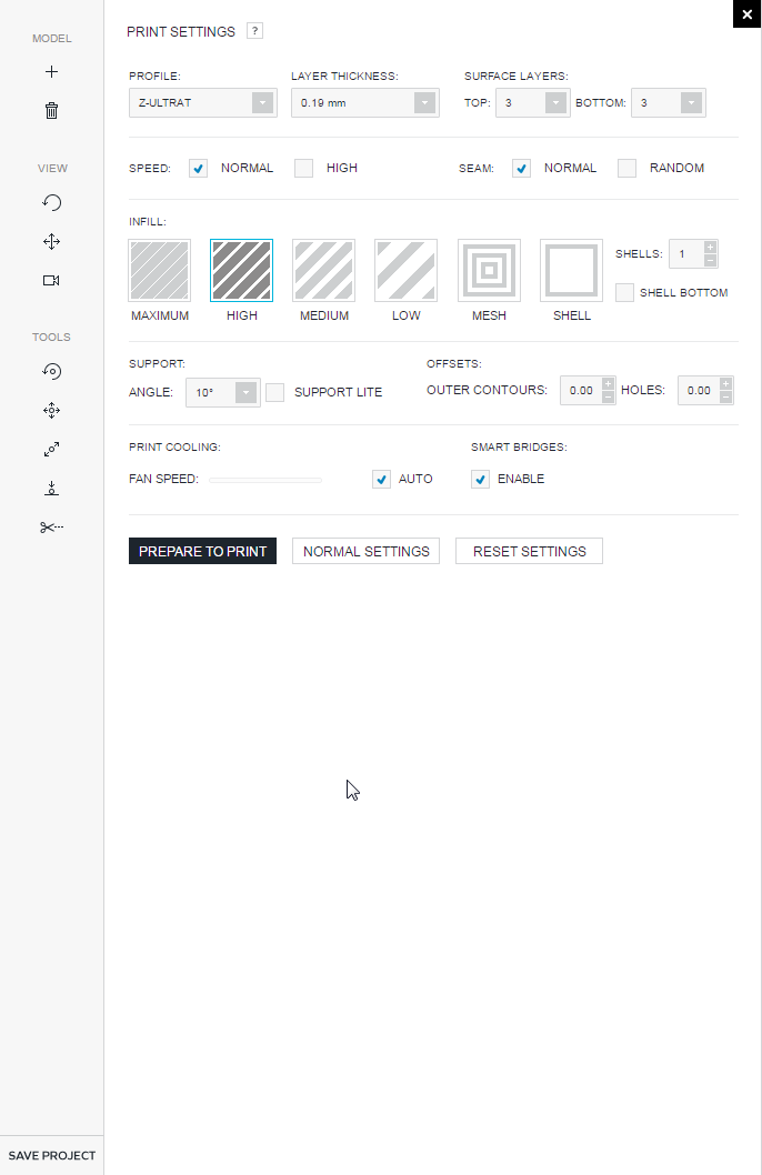
I would try printing some samples with different slicer options. For example could be a nice chance that 0.4 is the perfect extrusion width because of the extruder’s nozzle.
Make a cube with four different walls, lets say, 0.4, 0.8, 1.2, 1.6, then print that using different shell number from the advanced slicing options. Let me know.
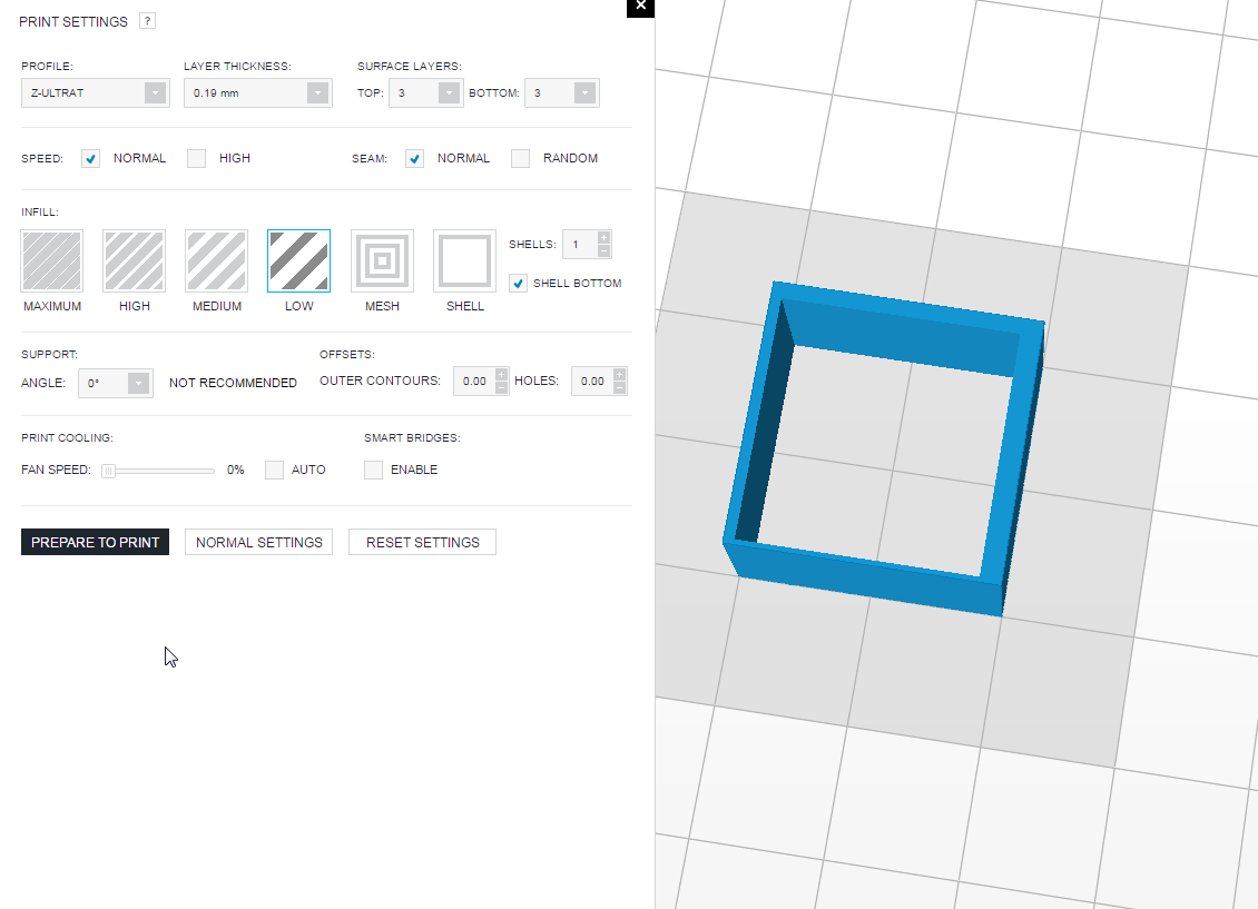
Edit: Ok... i set the 0,4 wall to 0,45 an now the software slice the part. So i think 0,45 is the widht of the software/printer. How can i use this knowledge for modeling parts?
Edit: Ok... i set the 0,4 wall to 0,45 an now the software slice the part. So i think 0,45 is the widht of the software/printer. How can i use this knowledge for modeling parts?
That means you must design walls larger then 0.45 mm, but I am not sure that the extrusion width is 0.45 mm.
