I also ordered some ball bearing fans. The ones on mine were sleeve bearing and they got noisy very quickly. Sleeve bearing is not the best choice for a horizontal installation.
Excellent, nice work. I really like being able to adjust airflow during a print rather than at slice time; same with temperature, as I can with the hardware temp control on my Ups. Sometimes low-tech is better.
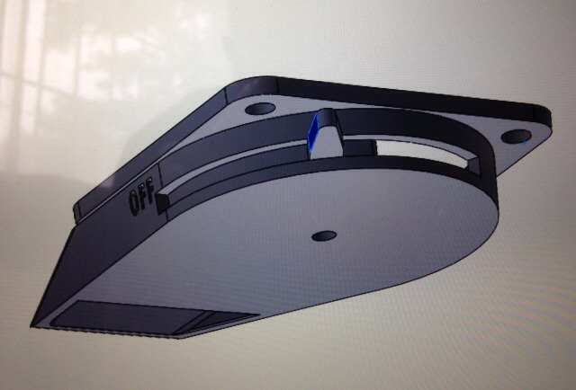
Did you try to make an extra air outlet, controled by lever as on image, but on oppositive side, so half, or 1/4 or 1/x of air can "escape" with extra hole? Because I'm afraid that closing the only hole may just make air to go faster (Bernoulini law of flow), and covering the hole may end up with redirecting the flow, is some situations the air will go on side of the nozzle and in the end not cooling the filament at all.
Today I spent 11 hours flying on paraglide, so most of the day I was breathing thinner air, so I may talk bosh ;) But I hope you know what I mean :)
I know exactly what you mean. I already have designed a version with bleed openings on the opposite side (controlled by the same shutter). I will test this version as well. But I’m not too concerned about speed increase when reducing the flow area. The flow is very turbulent anyway and the axial fan can’t really create any significant static pressure. It just gradually stalls out.
My concern with the bleed holes is that they may create unwanted air movement in the build chamber. It would be only to the right side but with an enclosure it may cause minimal heat loss… Not sure though.
OK, here you go… the first versions for you to try out
UPDATE: removed download until I have a better design. The current one hits the platform connector!!!
The folder contains the lever, the rotor, and two shroud versions…one with bleed holes and one without. Try them both and let me know which one works better for you. The one with the bleed holes is new and I did not print it yet…
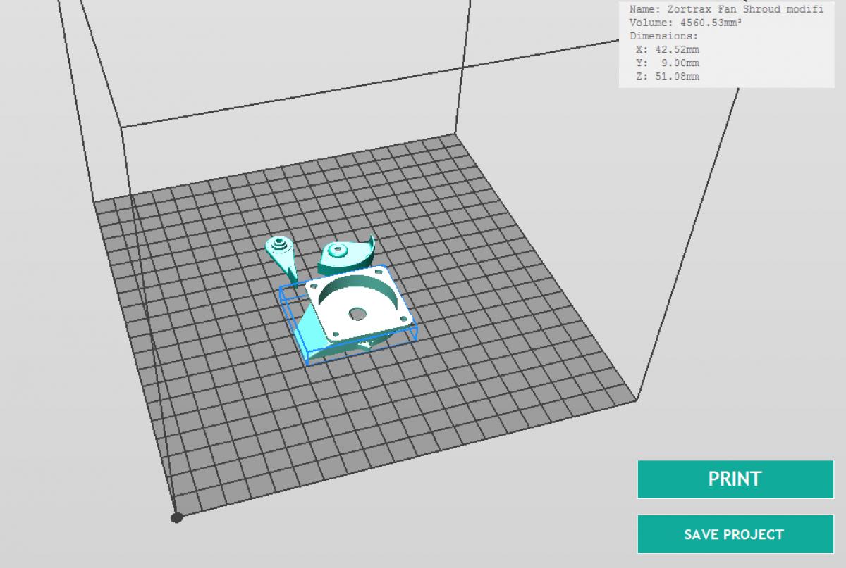
The picture below shows the positioning on the platform. This worked best for me considering seam position, etc.
Settings: 0.14mm, full infill, normal speed, 20% support, 100% fan, the rest is default (no offsets…I tweaked the file to fit without offsets)
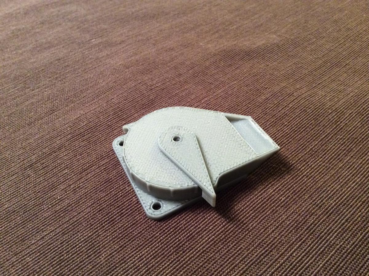
If your printer prints like mine you should only need some minor clean up (seams, blobs) end everything should fit.
The support inside needs some razor blade work but then it comes out without issues.
Use a short M3 button head screw to mount the lever to the rotor. By tightening the screw you also adjust the friction of the lever.
When you mount the shroud to the fan put the rear right screw in first…it has to clear the little stopper. You will see what I mean when you put it together.
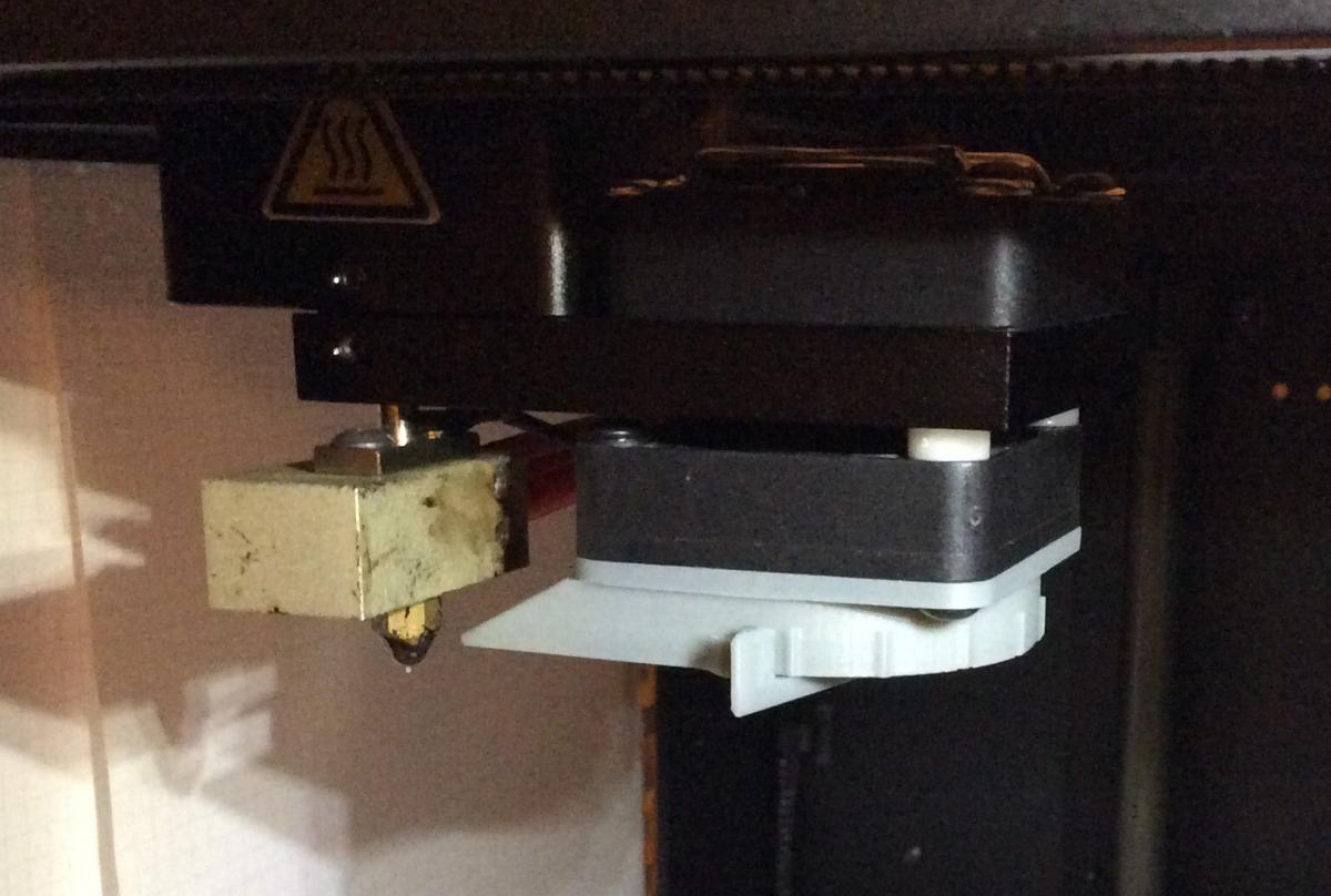
Also make sure the bottom with the lever clears and still sits higher than the nozzle tip…should be fine with the stock nozzle but if you use a shorter nozzle it might be tight!!!
Have fun and constructive feedback is appreciated!

