I am currently thinking about designing an improved dual fan shroud.
The original design from cesar is great, but the fan can hit the stepper motor in theory. I was not brave enough to print something in the back left corner to verify this though.
Another problem I had was that the cables coming out of the hotend for heater and temperature sensor are sometimes touching the plastic piece connecting the two fan shrouds and can bend it down a little. Then you are back to fan shroud hitting board connector. And if you are a neat-freak like me, you have the wires of the fan crossing the wires of the temperature sensor.
While the latter is shielded in theory it looks as if I still managed to produce some odd cross coupling that made a few prints fail.
So to sum it up.. The left fan shroud should go 5mm to the front, and the connection of the left and right and cabling shroud should also be at the front, out of harms way - the stepper motor and the cables coming out of the hotend. The only drawback is that the hotend is now in the way, so I was thinking about a few cm 10x10mm square aluminium tube, that connects left and right fan shroud at the front and sits above the hotend.
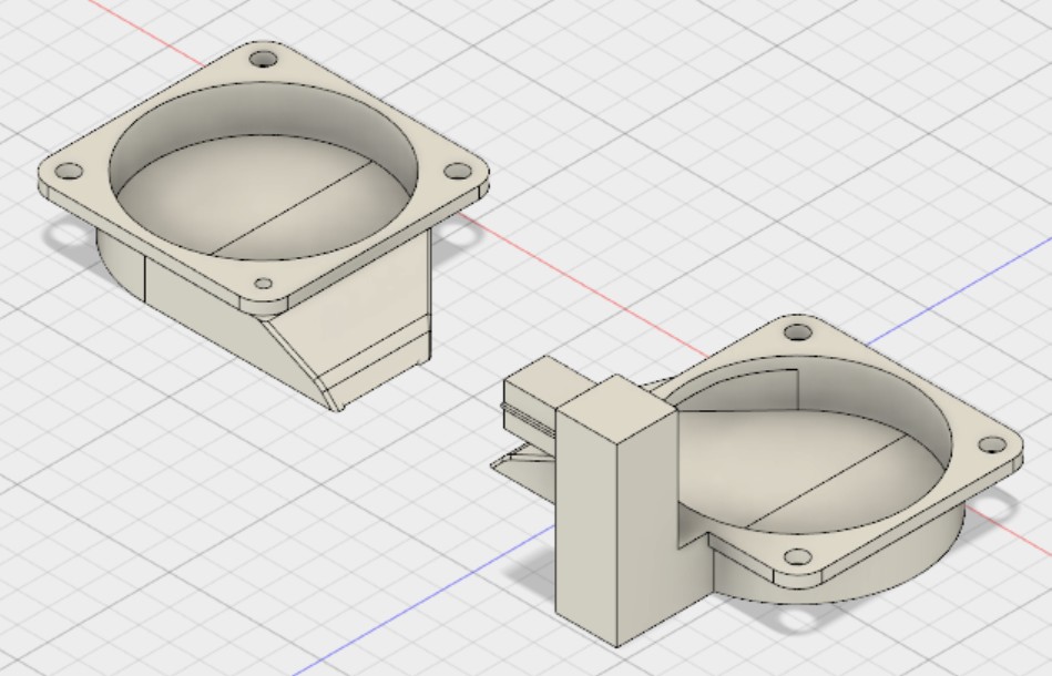
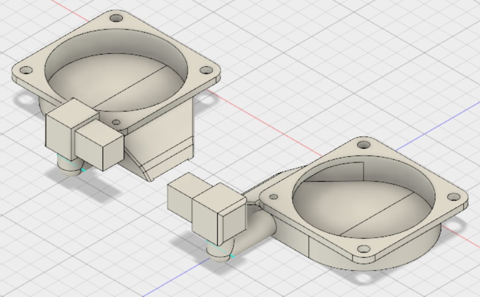
I already re-modelled the fan shroud in Autodesk Fusion 360 as best as I could and just played with the connecting bit. It will work, but oh boy does it looks sh*t.
I was also thiking about it. I like the Idea with the aluminium rod because my fanshroud already droped or bent down. can you show some pictures of you current design?
At the moment I cannot see how any fan-shroud sitting in parallel to the right one will not collide with the stepper motor. Or does the head not go "all the way back" during normal operation?
One problem which I saw when fiddling with my "aluminium rod" idea was that the holes for the screws to unmounts the hotend are covered. I see your model has the same problem.
So I thought it is better to have my "square or L-shaped" aluminium connector more or less on the same level as the hotend-block sitting in front of the hotend, or in case of the L-Shaped bit, sitting with about 5mm distance parallel to the
front and top of the hotend-block.
Sorry for the slow reply. There is never enough time to do all the nothing you want.
(I "HAD TO" solder a TTL RS232 Uart onto my Fritz-Box DSL router, then I "HAVE TO" turn an old Alix board into a pfSense Firewall and on top of that a bit of Leisure 3D Printing design...
Ah yes and then I started looking (much too late) into Bitcoin / Ethereum just to understand how it works in principle. So there is a Cubieboard2 to be turned into a Node just for fun maybe.
Any my Paris Lamp print is also still pending...)
Tobias <- Another 30min work, then home and catching up on ironing *g*
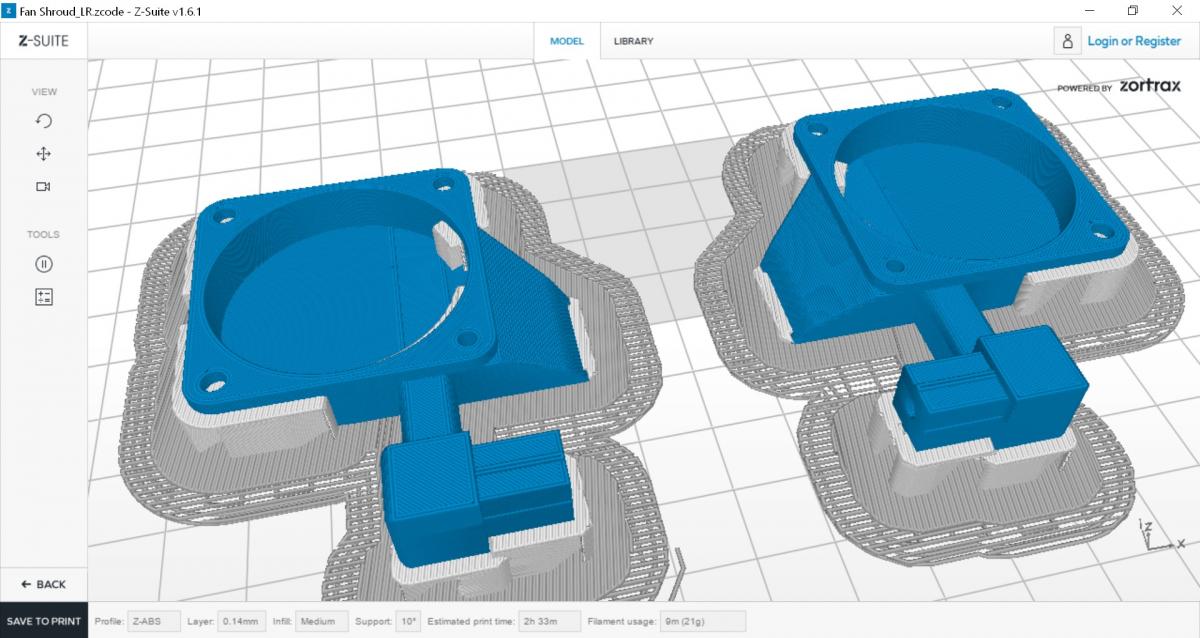
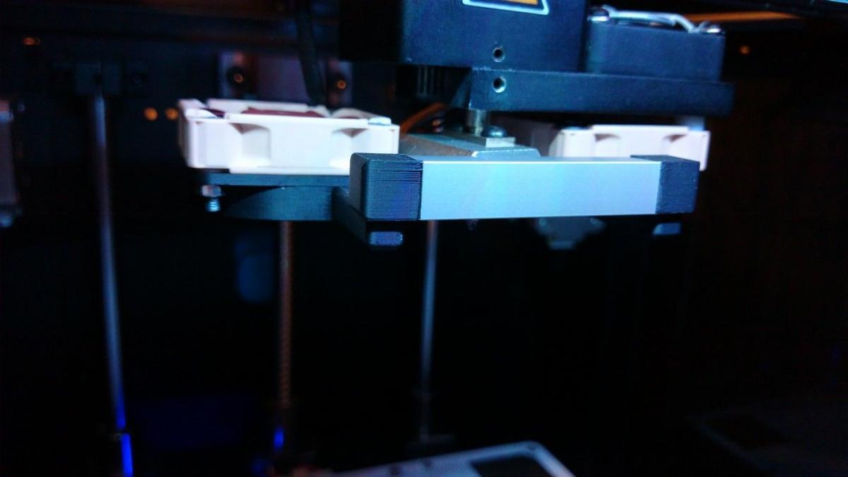
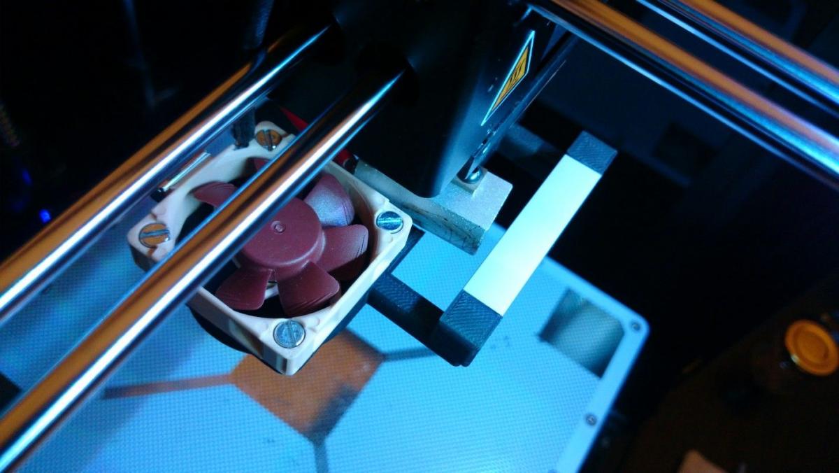
Managed to finally print a prototype and screw it on.
(Yes my Hotend is a bit wonky, that's how the printer came back from service. Guess they screwed it in extra-tight to fix any potential under extrusion problems.)
