Hi ChunkyPastaSauce,
Thank you very much for detailed support!
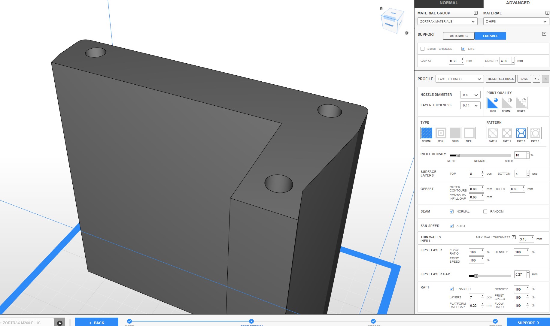
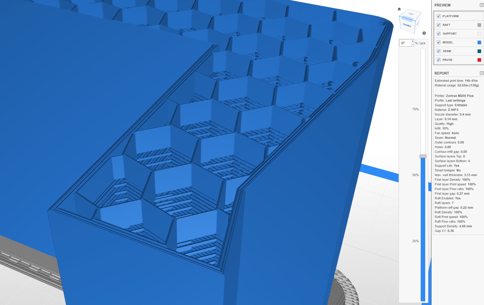
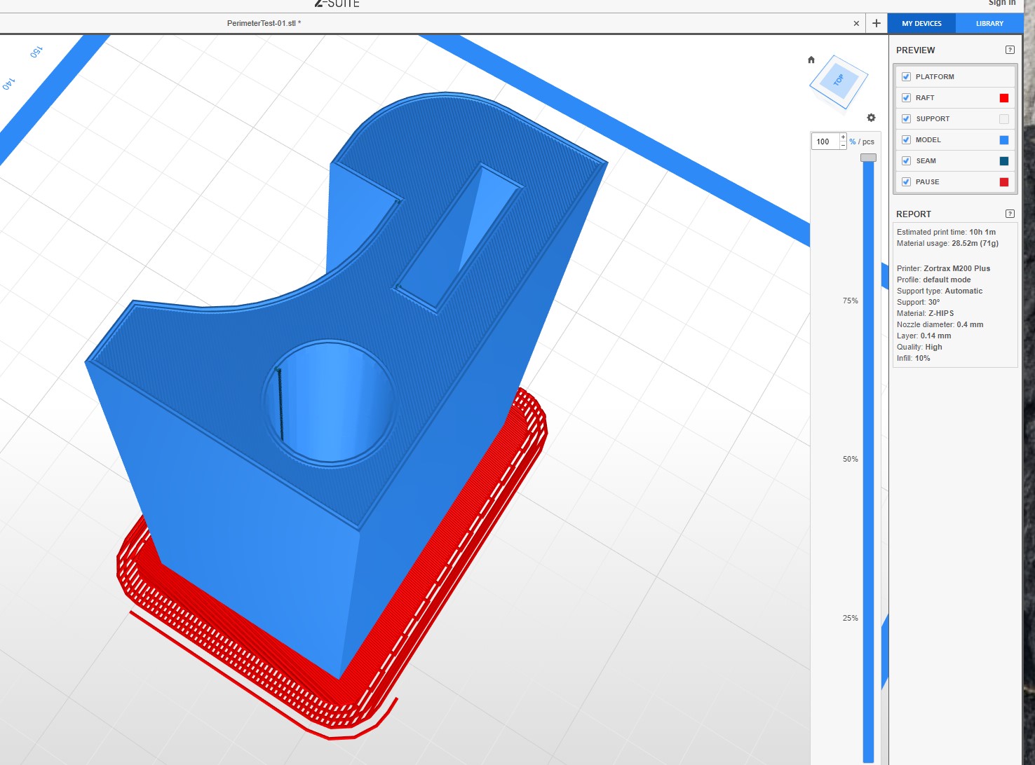
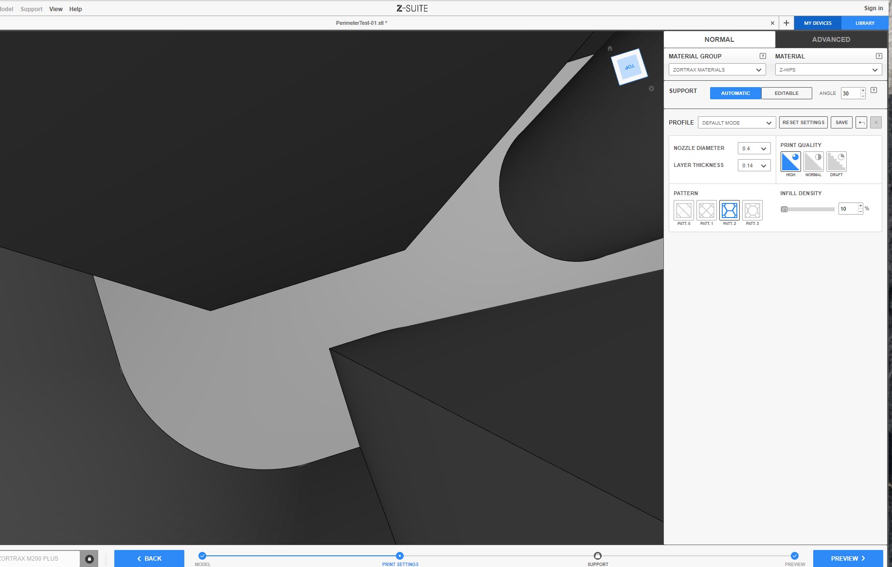
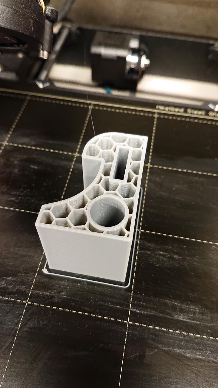
Nothing looks wrong to me when slicing model.
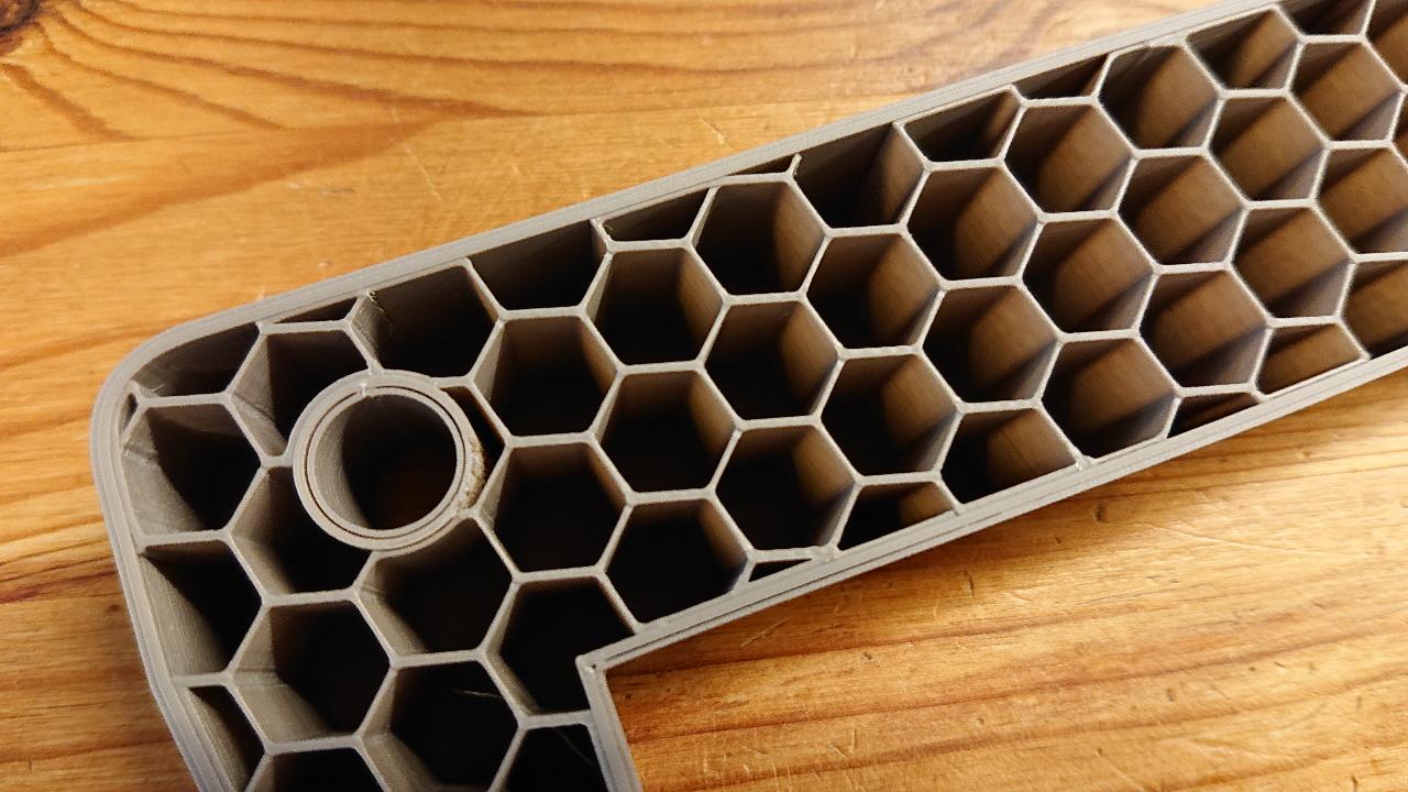
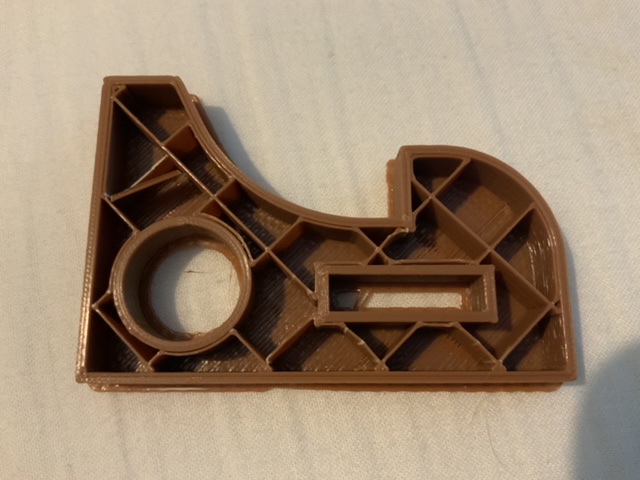
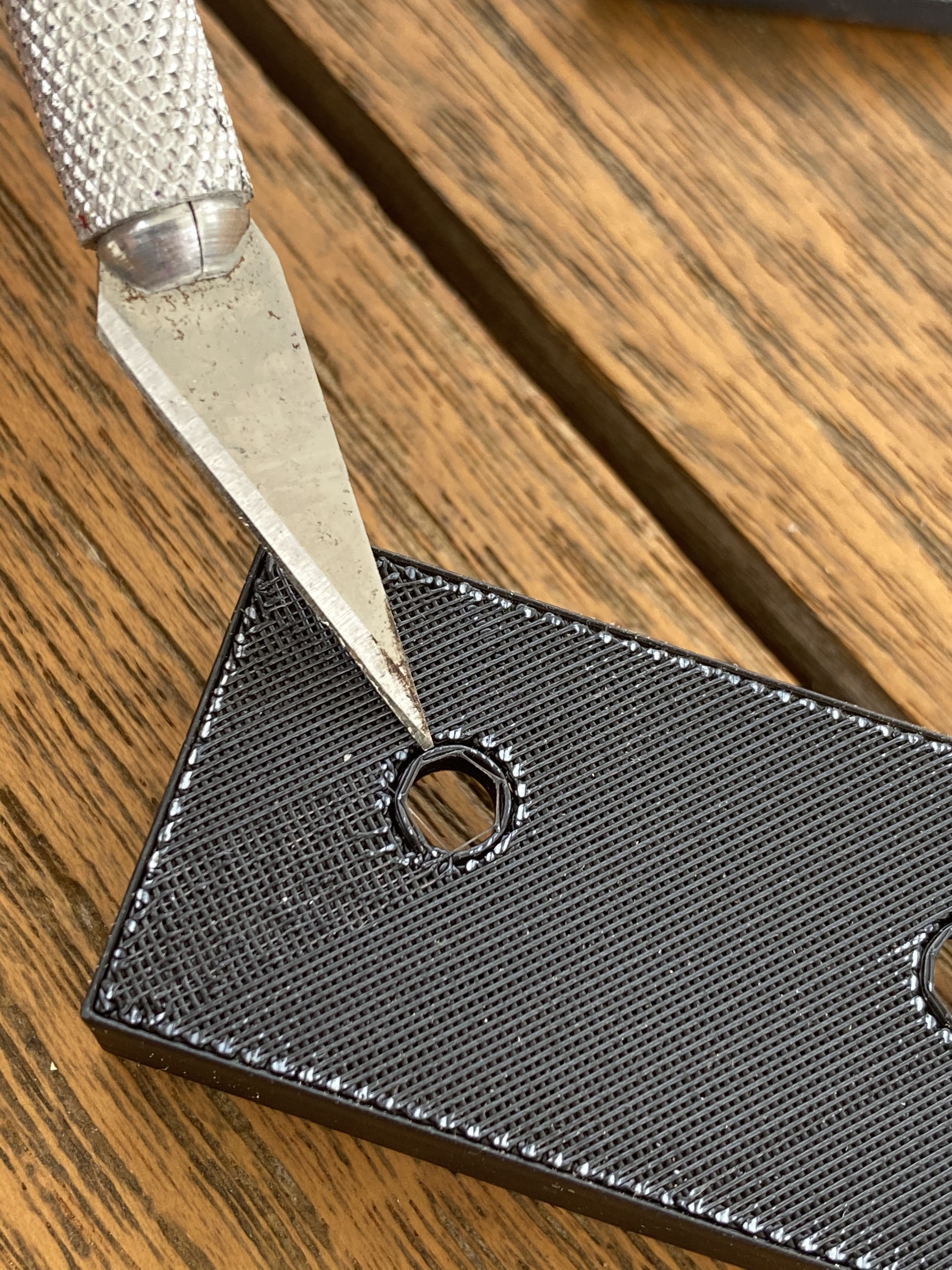
It kinda looks like you have a small gap in certain places around holes on top from your photo too?
Yes, there is also gap around holes. I have noticed this from the days of M200 and thought that this is the characteristic of Zortrax way, but this is problem, too.
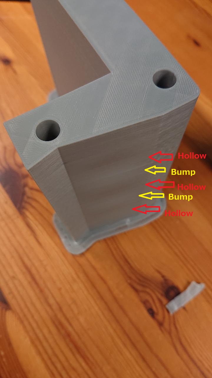
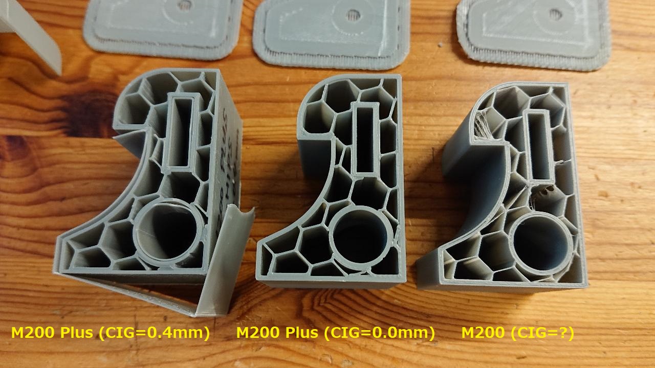
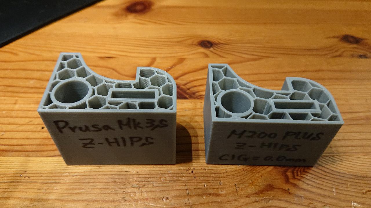
I can show you more pictures about this as bellow.
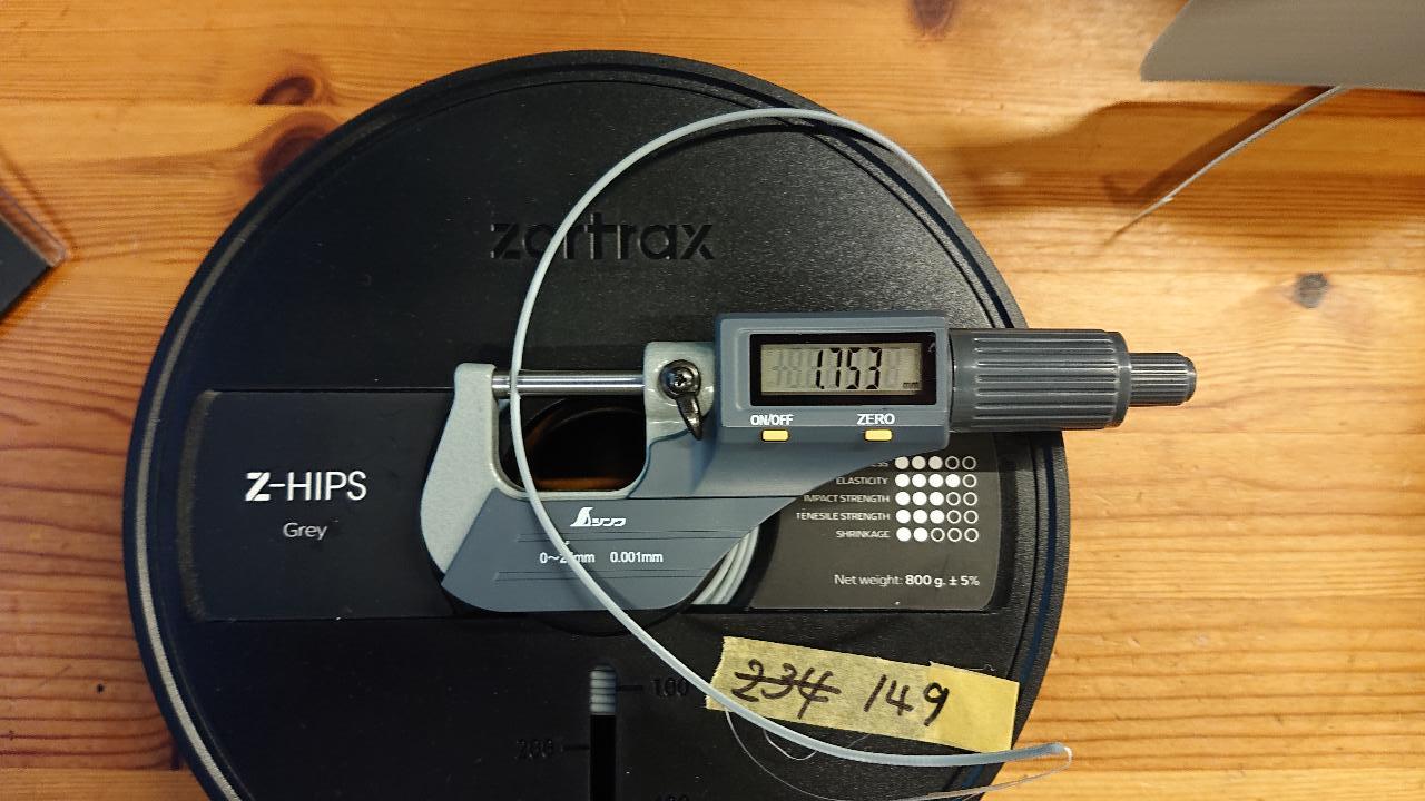
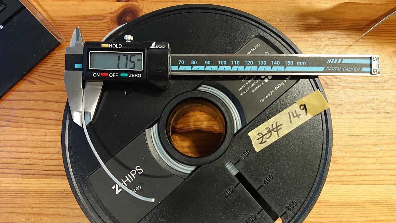
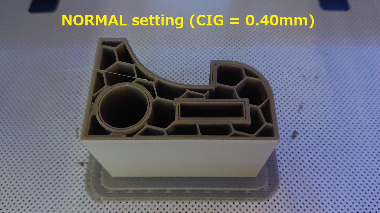
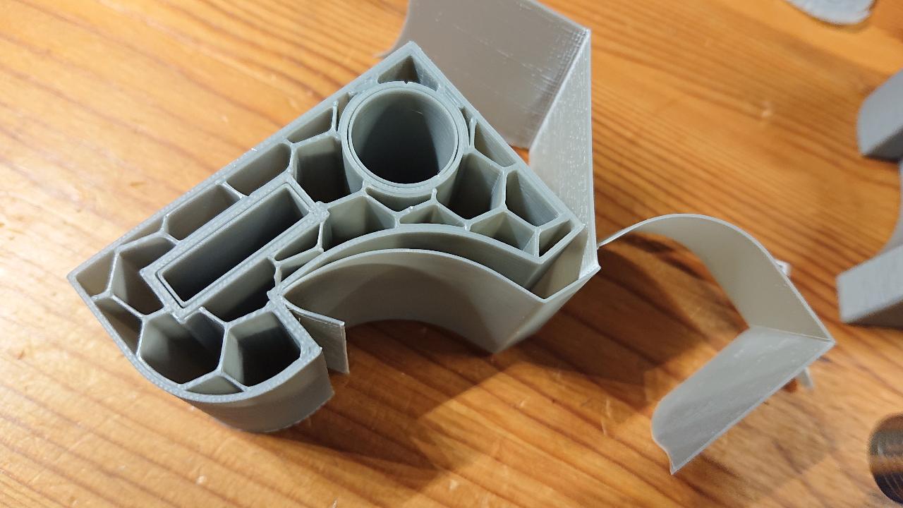
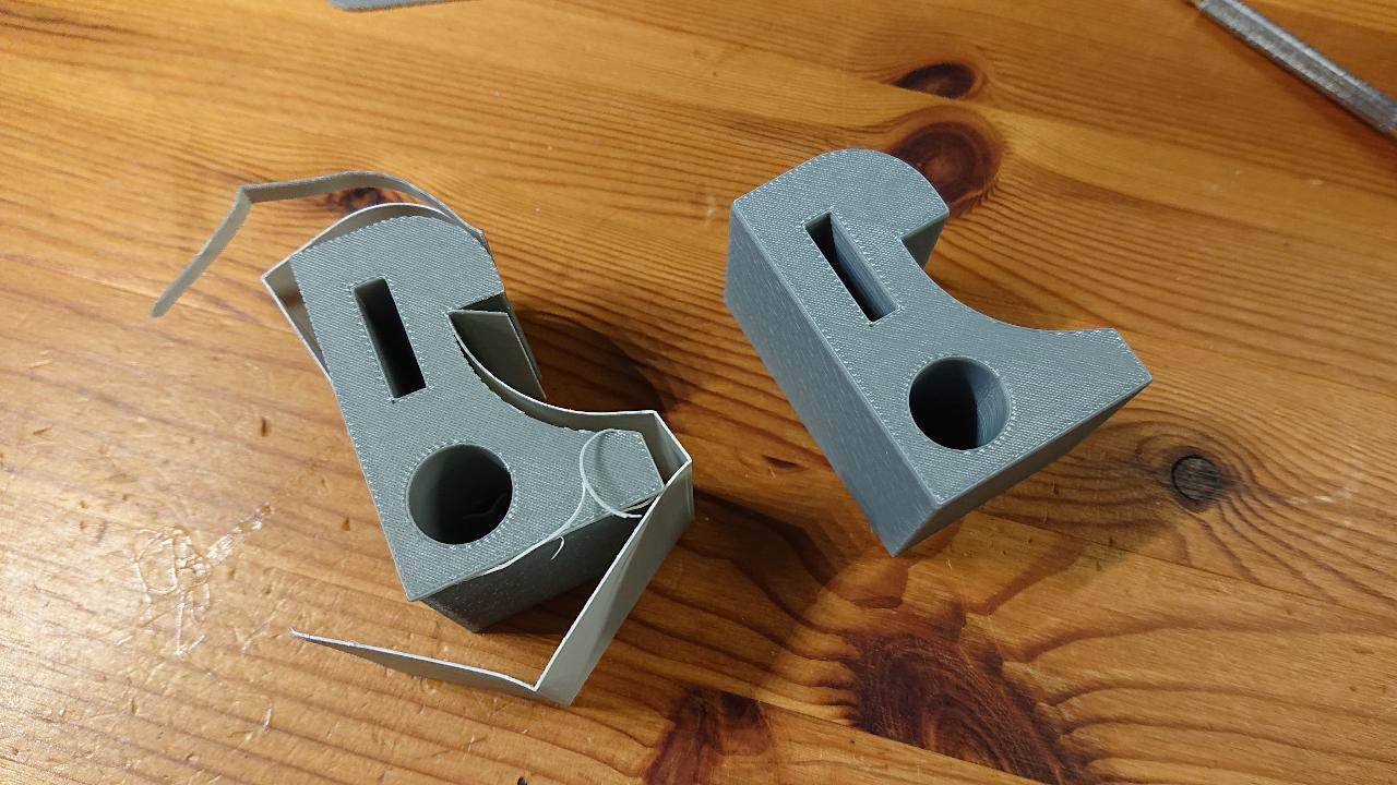
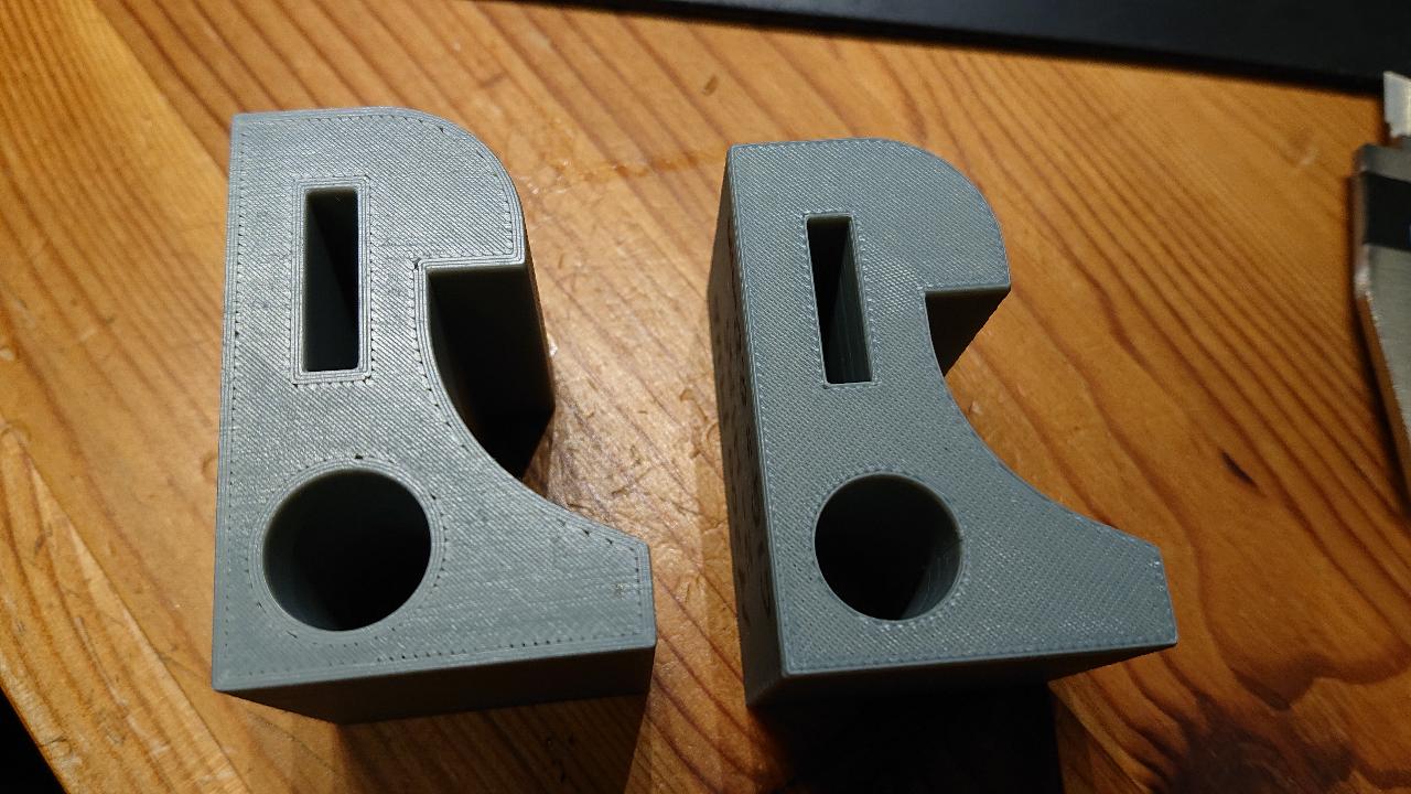
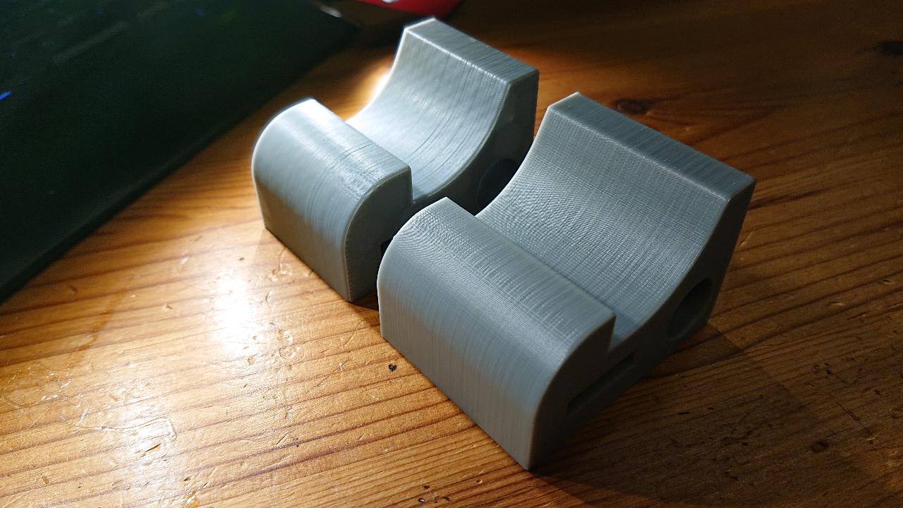
This is the one you mentioned. (This is Z-HIPS)
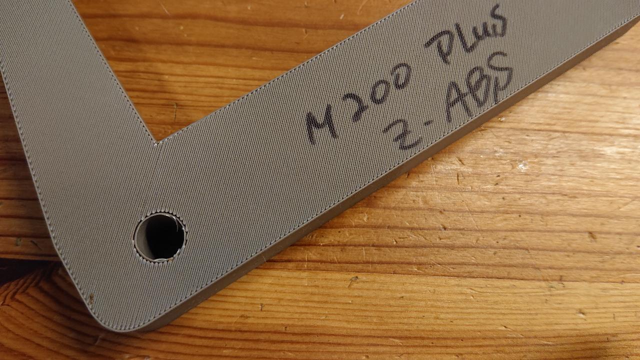
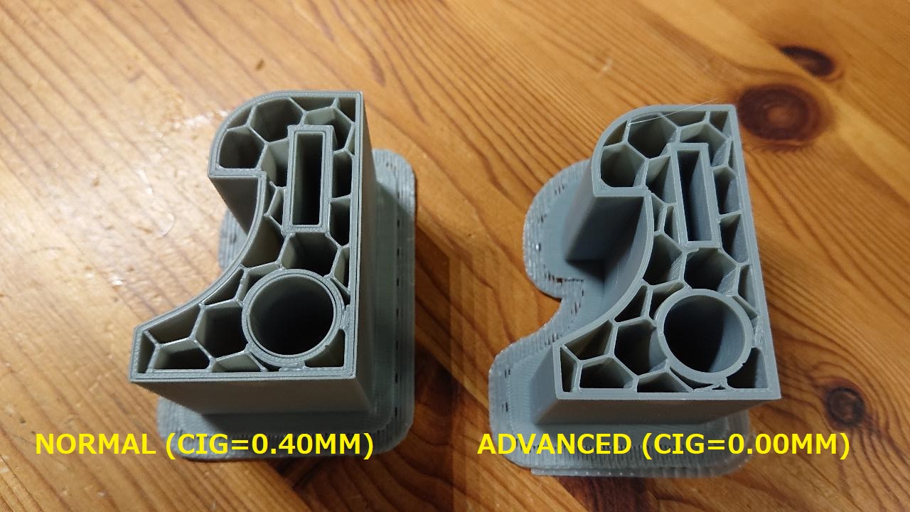
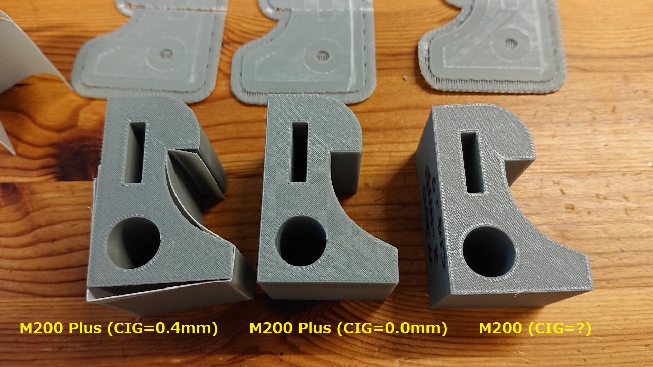
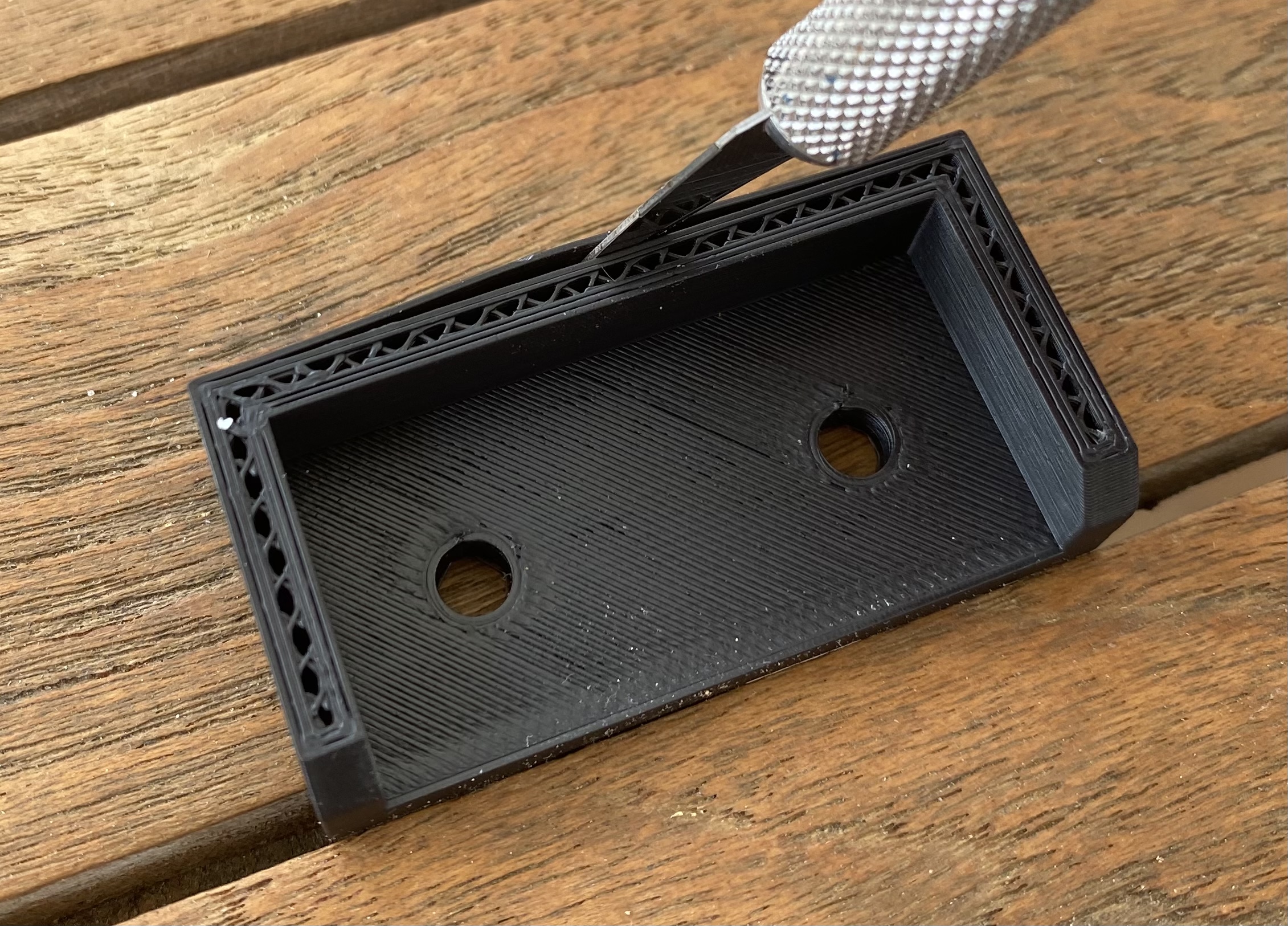
The following examples are by Z-ABS.
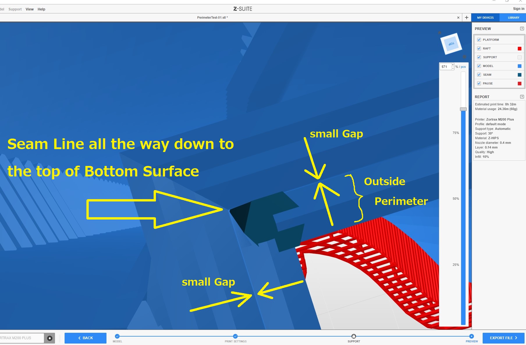
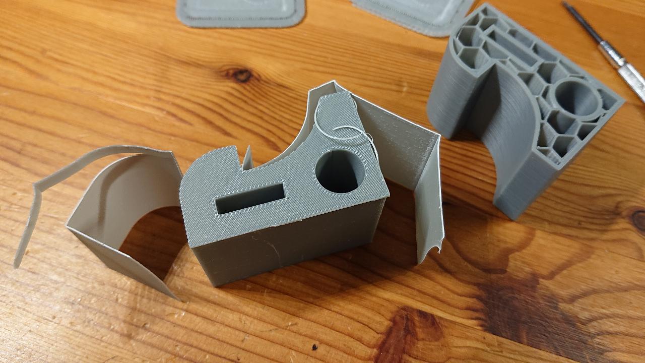
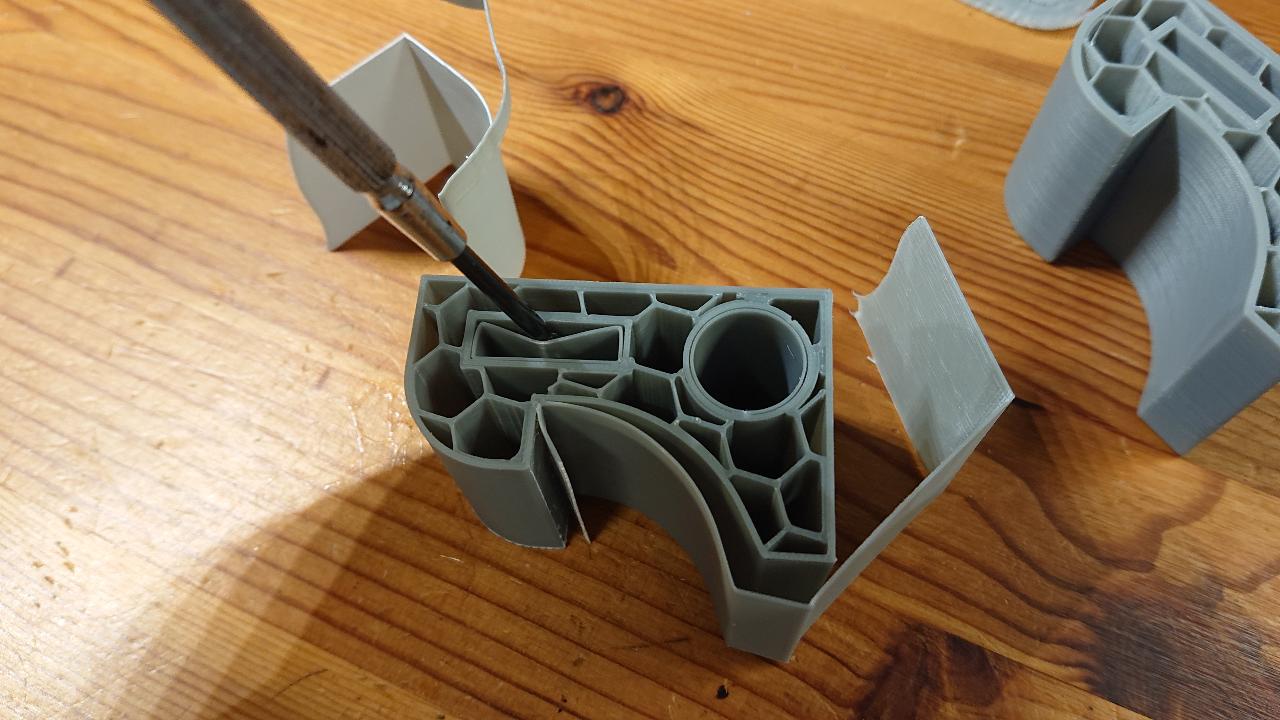
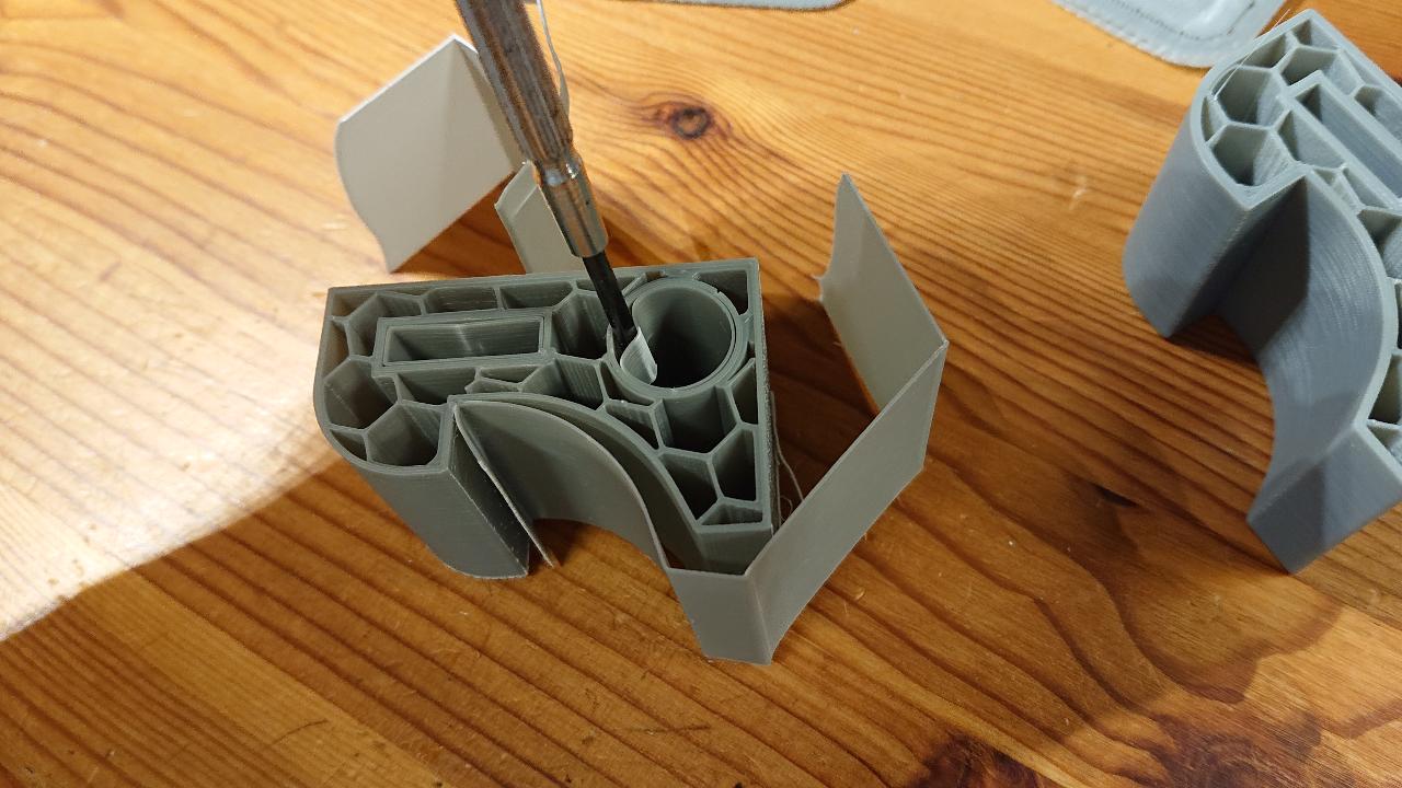
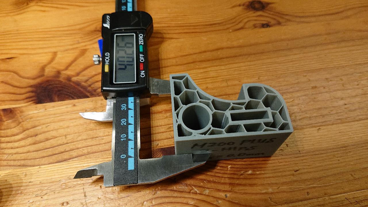
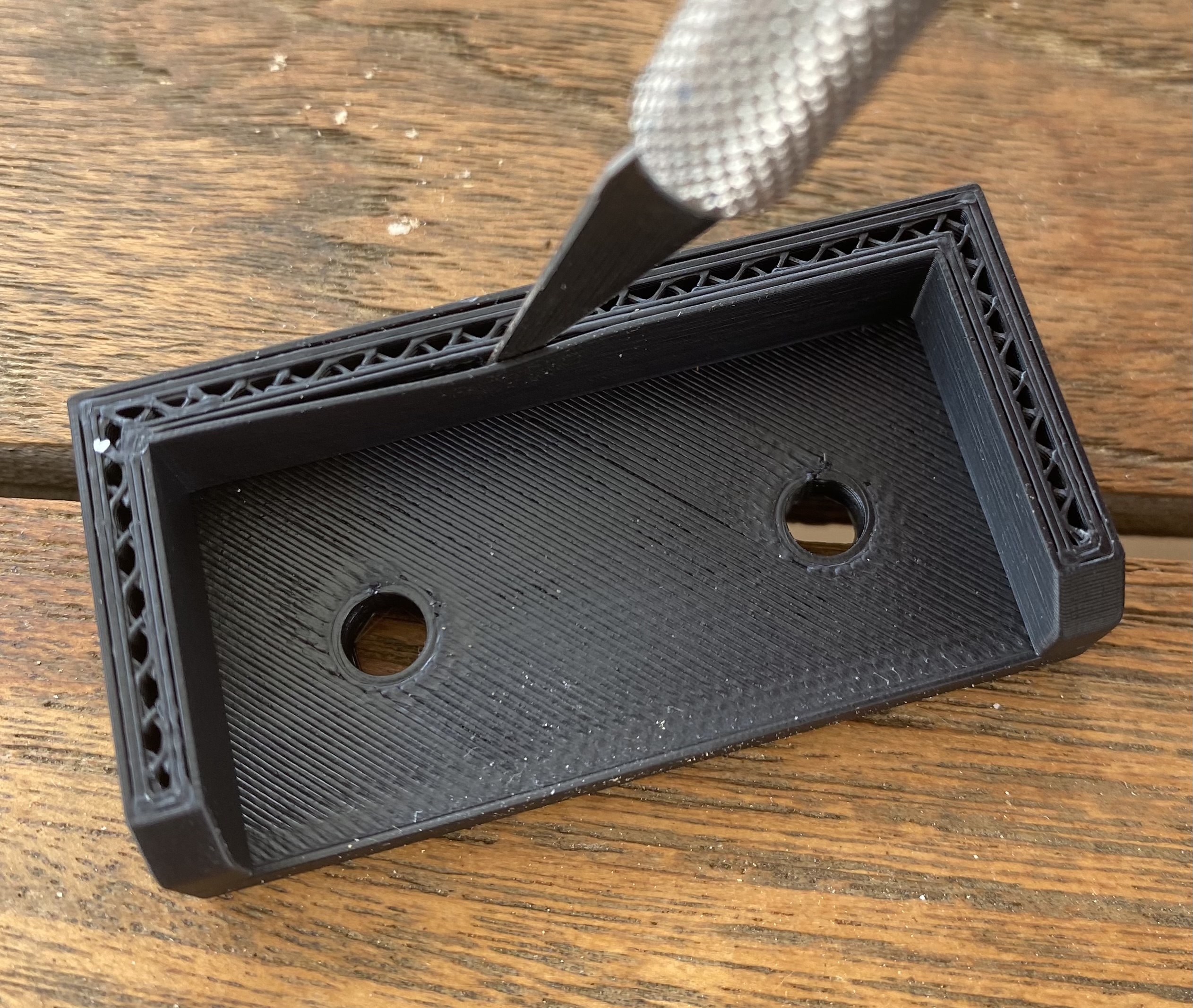
We can also see the outer perimeter separation, too!
Assuming the nozzle is clear, I’d try increasing the flow ratio to widen the perimeters or maybe increasing temperature.
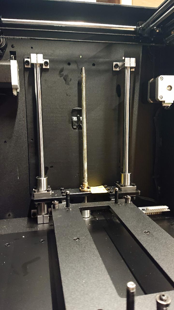
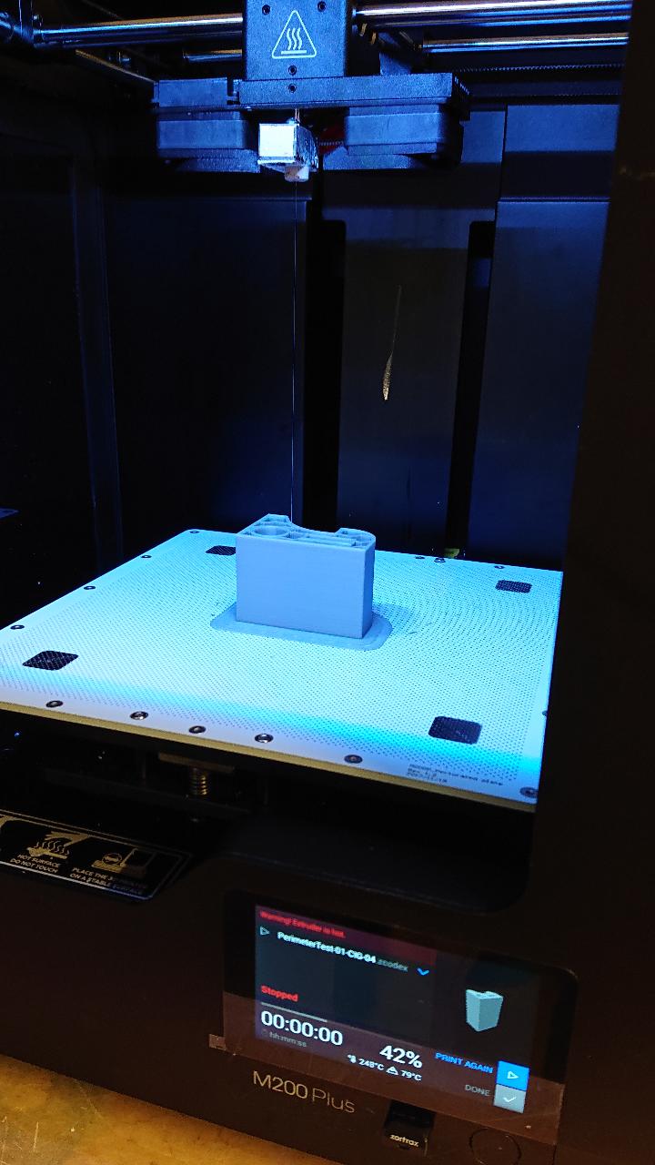
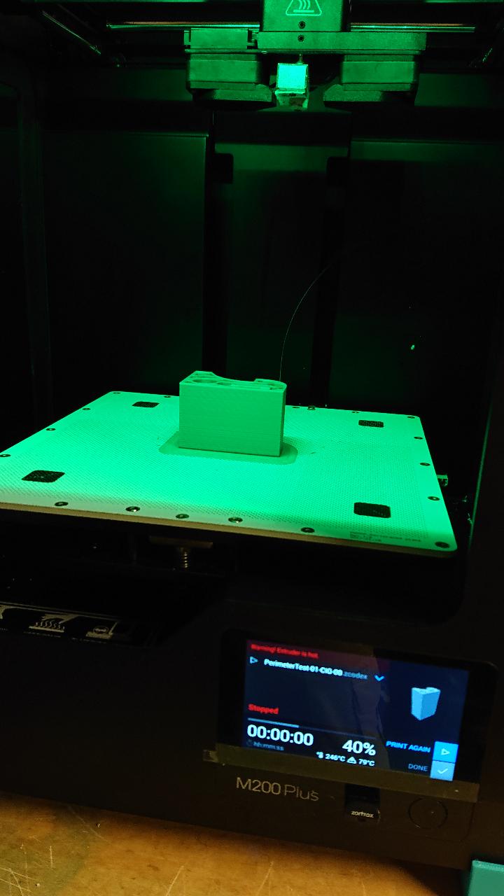
As you may find in other thread “Print stops on the way before completion”, I have had a problem for longer printing, I have changed for new nozzle and its cover, maintained all the axis, belt tension …
So machine should be ok, I think.
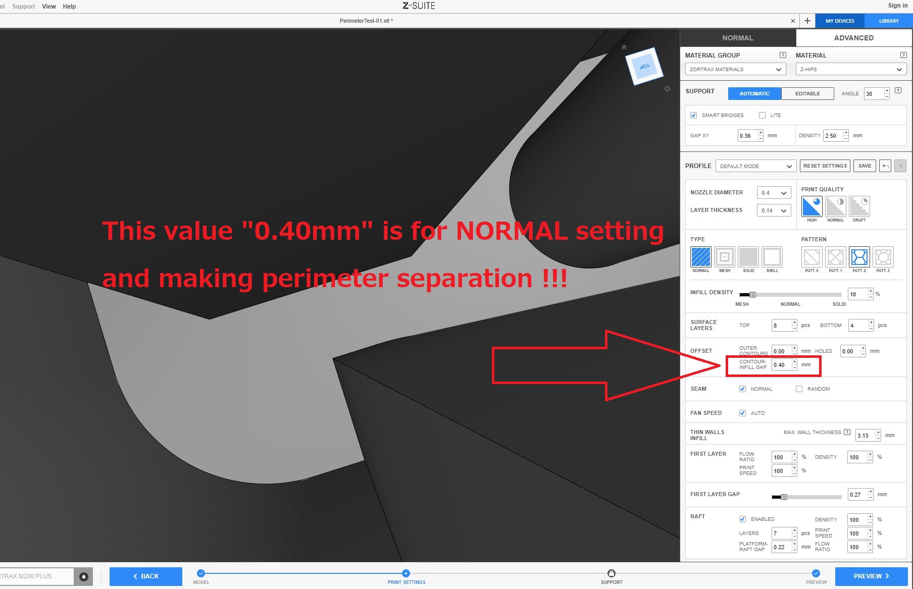
Since I am using Zortraz materials, Z-HIPS and Z-ABS in my case, I usually use the default setting for Zortrax materials. In this case you have no control about temperature. Otherwise we have to use external setting… I have had feeling that Zortrax machine is not good at temperature control especially for extruder and that tendency appears clearly for PLA printing. Thai is why I use MicroSwiss Hotend for M200 since I use M200 for PLA printing sometime when I need more printers. Usually I use Prusa Mk3S, Anycubic i3 Mega, CR-10 and other for PLA printing. Also we can not control flow ratio for Zortrax materials, but only for the first layer.
It’s worth measuring the filament to check if it’s undersized. If it does this every print since you got the machine (and assuming it’s not normal for m200plus), then it’s possible for something like the extruder gear being slightly off size. Another possibility is the temperature being too low for some reason.
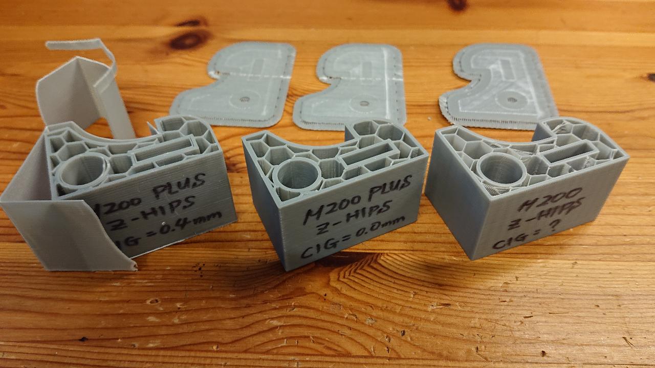
I think that this separation usually happens on M200 Plus, just I did not notice. If printing model is small and low height, it is hard to see if outer perimeter is detached …
I have also checked extruder gear and bearing next to it, they are all fine!
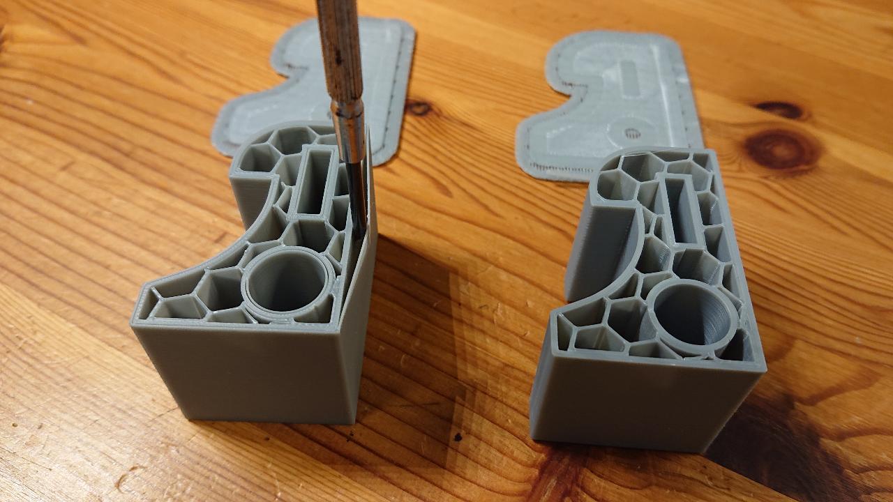
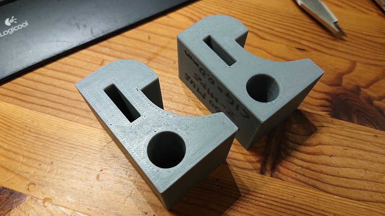
I think that this is the printing scheme problem. Therefore this should be fixed by tool path, extruder temperature, fan speed around these perimeter areas !!
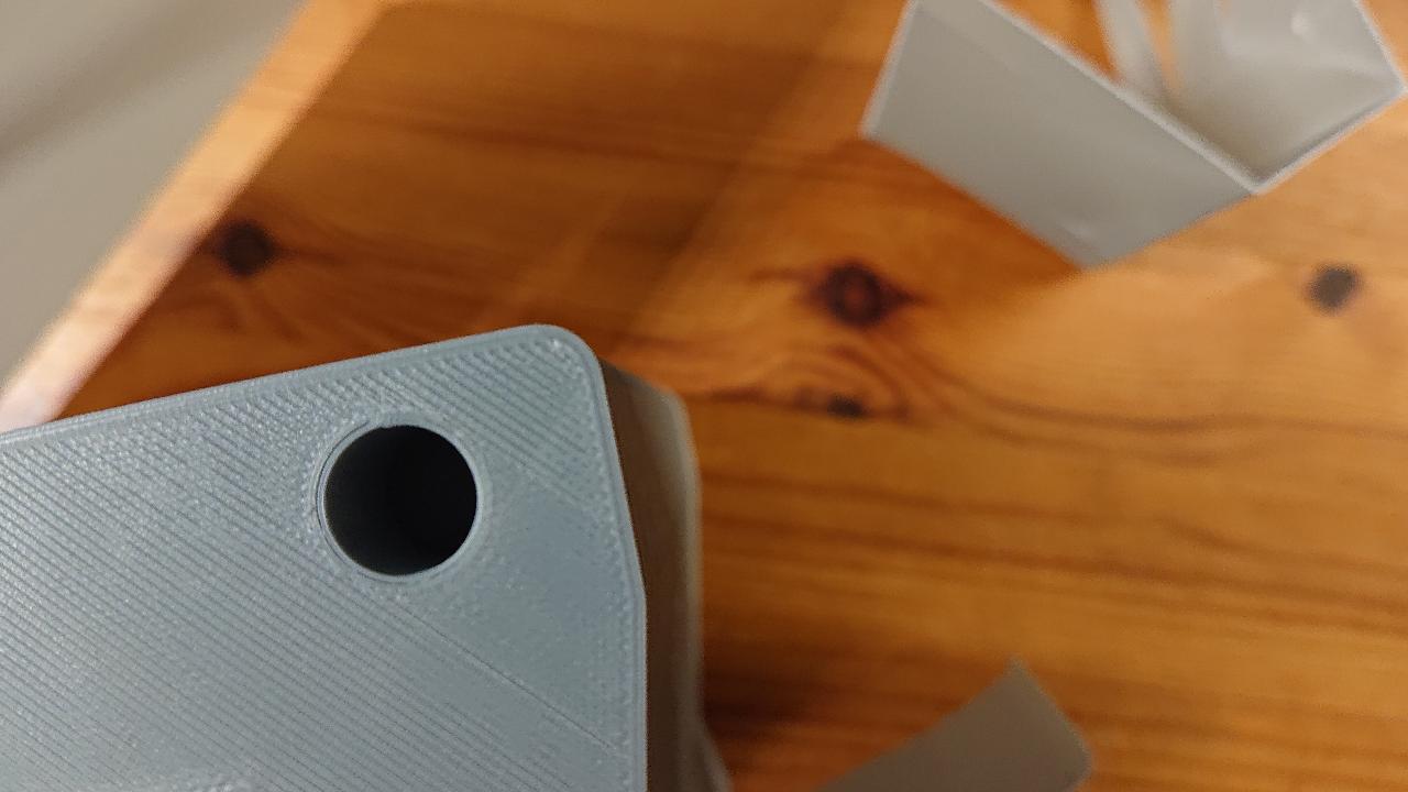
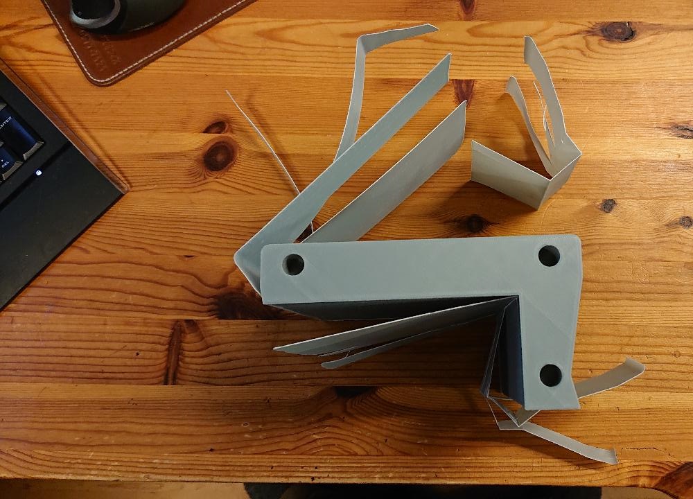
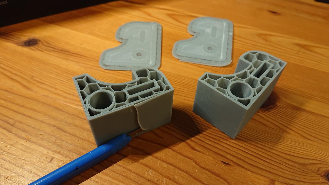
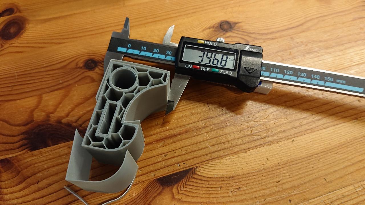
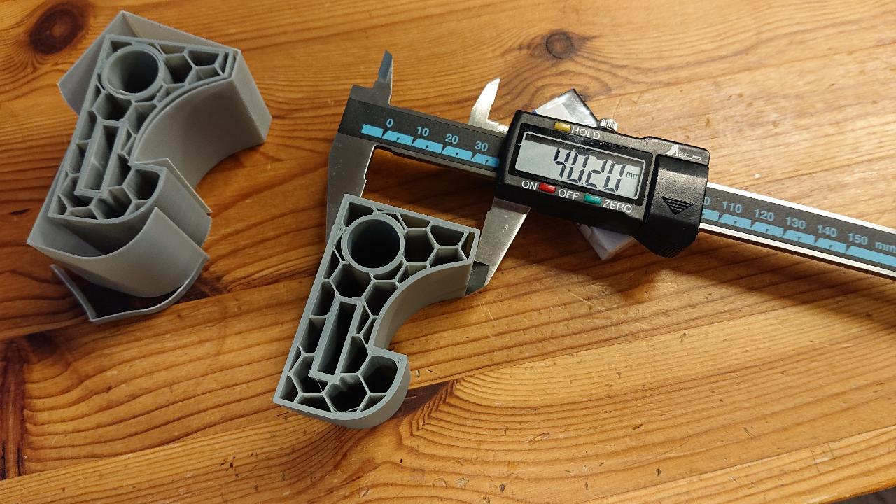
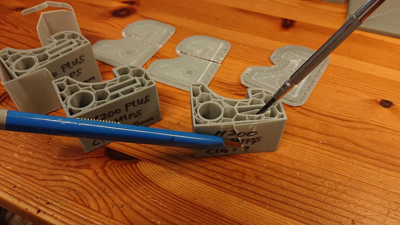
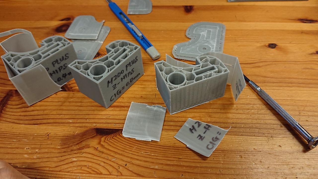
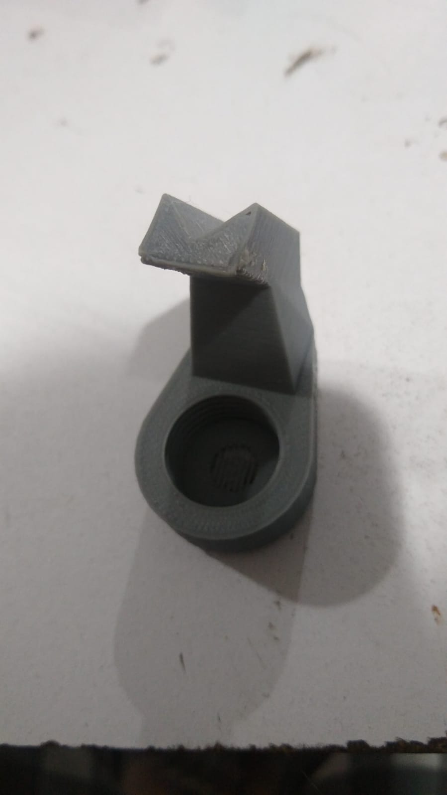
I can peel off all the face around except seam line as you see bellow.
I cannot use M200+ for the model with tall vertical surface …