If you create the lower support with Meshmixer (or something else, probably directly with the models source) then you can print the part without support and insert your magnet.
Have you just tried pausing the print and removing the support structure where you want to place the magnet and continuing printing?
Or If you design your part with a plug the same size as your magnet you want to place in there but leave a 0.4mm gap around the magnet plug, then when you print pause the print as soon as it has completed the magnet plug and remove the magnet plug and insert your magnet and continue printing. It is often difficult to remove a part that has been printed with the 0,4mm gap on a flat horizontal print, I would recommend you design the lower part of the magnet plug to be a compound curve but big enough to still accommodate your magnet.
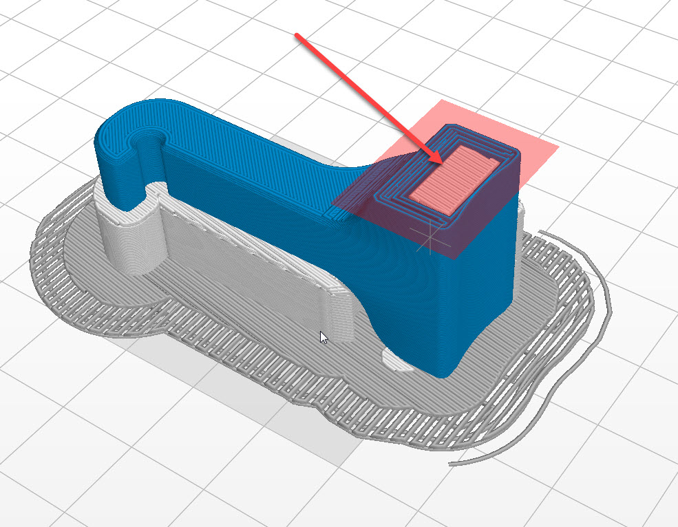
I myself would love this option to insert a bounding box that you could manipulate in Z-Suite which would ignore support structure being generated where ever this box is.
At the moment i have other parts that i drop a 1/4 inch thread female for tripod mount, i have to set a pause point and dig out the support which takes about 5 - 10 mins... unfortunately with so much time spent removing the support the bed is slightly adjusted which can then be seen in the layer.
please see picture of the bounding box idea. Unfortunately i think it would cost a fair amount of money for the programmers to implement this.
please see picture of the bounding box idea. Unfortunately i think it would cost a fair amount of money for the programmers to implement this.
It would need a CAD module for post-processing in Z-Suite since none of the file formats you use in 3D (and load into Z-Suite) is prepared to embed the information that such a feature would need.
I tried inserting some magnets in a part part-way through the print a while back and they got pulled out of the part by some sort of ferrous material in or near the hot end, though for the life of me I can't get a magnet to stick anywhere near the hot end now. The printer power is off now, but that shouldn't make a difference.
It's been a while so I don't remember the details, but as I recall, I had Z-Suite pause at an appropriate layer at the top of the magnet cavities, inserted the 20mm dia x 2mm thick magnets, and resumed printing. Shortly thereafter the magnets were yanked out of the print cavities before they could be sealed into place.
Maybe I imagined it - the same magnets don't seem to be attracted by anything in the vicinity of the hot end now, with the printer on, but idle.
I tried inserting some magnets in a part part-way through the print a while back and they got pulled out of the part by some sort of ferrous material in or near the hot end, though for the life of me I can't get a magnet to stick anywhere near the hot end now. The printer power is off now, but that shouldn't make a difference.
The screws that hold the fan are metallic and when the fan is running it does create a slight magnetic field
Do you have experience or settings for meshmixer to use with the M200?
How should i model the support in the cad system (gap, geometry, ...)? Do you have any idea?
No I have no experience doing this with meshmixer since I mostly print my own designs and because of that I can integrate such supports in the original CAD file.
Actually carbon1 described how to create such supports in CAD in a post before you asked me.
This is a printed wing nut with a standard M8 steel nut inserted part way through the print. The CAD drawing has a nut (just slightly bigger than the steel nut) with a 0.4mm gap all around the nut (the lower face of the nut is drawn with a curved surface) and a pause in the print to remove the dummy nut and insert the steel nut before continuing printing.
I have attached the STL so you can load it and split it to see the 0.4mm gap
This is a printed wing nut with a standard M8 steel nut inserted part way through the print. The CAD drawing has a nut (just slightly bigger than the steel nut) with a 0.4mm gap all around the nut (the lower face of the nut is drawn with a curved surface) and a pause in the print to remove the dummy nut and insert the steel nut before continuing printing.
And what makes you actually think that this plug is needed to be able placing a nut there?
I would just set support to 0 and print it with the pause.
And what makes you actually think that this plug is needed to be able placing a nut there?
I would just set support to 0 and print it with the pause.
I have tried that, but if you use 0 support then any other overhangs in the part will loose detail on the overhangs where you would normally require support.
On more complicated parts having removable plugs drawn in the CAD drawing makes it easier to remove the section to be replaced with an object than removing support and you can still have good support for the rest of the structure.
I have tried that, but if you use 0 support then any other overhangs in the part will loose detail on the overhangs where you would normally require support.
o.k., didn't see that overhangs, downloaded your model only now. Turning the part upside down would probably not help much because of the rounded edges.
This is where a fancy design needs added support to fool the slicer. I do this also if certain surface quality is wanted and Z-Suite added support ruins that surface.