Because I don't have an artistic bone in my body and don't have some of the amazing CAD skills of other members, I've never posted up here in the printroom.
This is my fully reworked version of the "Tom Tri Track" off Thingiverse.
http://www.thingiverse.com/thing:19170/#remixes
Like so many things found there, it just didn't really fit well and was more a concept than a working design, so I've remade every single part and added a few of my own.
It will be (I hope) a fully autonomous obstacle avoidance robot, via the twin sonar sensors on the front and Arduino Uno computer, driving a couple of continuous rotation servos as motors.
It rolls on 608 bearings on 8mm axles and is quite sturdy.
It's about 19cm x 19cm, and must be close to a kilo in weight.
[url=http://s1275.photobucket.com/user/azadani/media/002_6.jpg.html]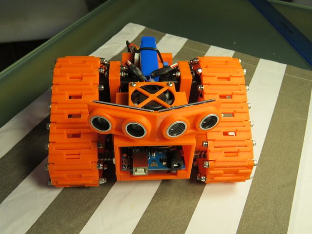 [/URL]
[url=http://s1275.photobucket.com/user/azadani/media/003_6.jpg.html]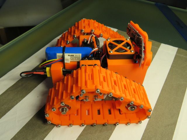 [/URL]
[url=http://s1275.photobucket.com/user/azadani/media/004_3.jpg.html]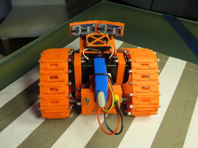 [/URL]
[url=http://s1275.photobucket.com/user/azadani/media/003_6.jpg.html][/URL]
Any Arduino programming buffs out there who'd help do me a sketch for this?
I'm really struggling with understanding the code side of it.
Have you tried "Stationary.ino" in the thing file list? That is the basic Arduino code. I can answer question if you have them
Have you tried "Stationary.ino" in the thing file list? That is the basic Arduino code. I can answer question if you have them
No I haven't yet, I do have it here.
To be honest I can't overstate how bad I am with that sort of thing. I'll have another look.
First problem I see is that he used Parallax sensors that were really expensive, where I used the garden variety "HC-SR04" sensors for 4 bucks each.
The "04" is really popular but has 2 pins, "echo and trigger". The parallax (60 bucks) has one "ping" pin.
Possibly if I can change the sensor code to use the "04" and keep all the same values this would work.
I have it connected as follows at the moment:
Left servo signal. Pin 4
Right servo signal. Pin 5
Left sonar echo. Pin 6
Left sonar trigger. Pin 7
Right sonar echo. Pin 8
Right sonar trigger. Pin 9
All digital pins, obviously I've got power and ground connected to the sonars as well. Servo power is feed from a separate 3A UBEC.
I would appreciate any help with that actually.
Sure, I can help you. Actually I think I have a set of 8-10 of the originals, before Arduino was around. They were made by devantech, now cloned by others. I have some work I need to catch up on for the day, but I will help later.
Definitely useful now and easiest to understand: http://www.robot-electronics.co.uk/htm/arduino_examples.htm#SRF04%20Ultrasonic%20Rangerand http://www.robot-electronics.co.uk/files/arduino_srf04.ino
http://wiki.iteadstudio.com/Ultrasonic_Ranging_Module_HC-SR04
Probably useful in the future (might be confusing now) http://playground.arduino.cc/Code/NewPing
Also the servo wont work on pin 4, only one of these 3, 5, 6, 9, 10, and 11 (those pins have the hardware function).
Ah, OK.
I'll put the servos at 9 and 10 like the stationary sketch.
Cheers for that.
That link with the code looks handy.
So I'd just do it twice, once for the left and once for the right (named l and r) and cut and paster it over the ping section in stationary?
Obviously might be a little more complicated than that....
My understanding is that I have to range test both the sonar sensors first somehow, and that they need to pulse alternately so they don't "distract" each other?
Other than that my understanding is limited lol.